
User Manual

4:4
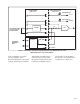
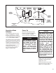
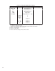
Table 4Ć2. Control Power Voltages.
Function
Terminal(s)
/Pin(s)
Nominal Values
(VDC)
Unregulated +20 VDC 256 +20 VDC +5%
Unregulated Ć20 VDC 271 Ć20 VDC +5%
Regulated +11.2 VDC 56 +11.2 VDC +5%
Regulated Ć11.2 VDC 71 Ć11.2 VDC +5%
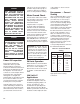
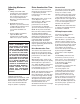
Drive SetĆUp Procedure
Basic Regulator Maximum
Safe Operating Adjustments
The following adjustments are
available on the Basic Regulator
(see Figure 4Ć3):
CAUTION: The following adjustĆ
ments are maximum safe operĆ
ating ranges. Potentiometers on
the regulator, particularly curĆ
rent limit, may exceed these
ranges. Failure to observe this
precaution could result in damĆ
age to, or destruction of, equipĆ
ment.
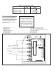
0
J8
COM
TEST
0
0
0
0
CTA
56
17
16
271
256
126
57
71
419
85
87
86
319
219
56
57
2.5
3.7
FDBK.
CLIP FOR
50HZ
J7
45
55
60
65
70
0
MAX. SPD.
MIN. SPD.
ACCEL. SPD.
DECEL. SPD.
I LIMIT
IR COMP
Maximum Speeed ā 50 to 100% of motor base speed........................................
Minimum Speed 0 to 100% of motor base speed.........................................
Current Limit 10 to 150% of armature voltage at rated load.............................................
IR Drop Compensation 0 to 2% of rated load....................................
Acceleration Rate āā0.5to 30 seconds........................................
Deceleration Rate āā0.5to 30 seconds........................................
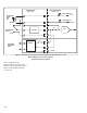
Figure 4Ć3. Regulator Function Potentiometers