
User Manual

4:7
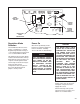
Adjusting Maximum
Speed
1. Initially set the MAX. SPD.
potentiometer on the Regulator
Board fully counterĆclockwise.
This should prevent the motor
from overspeeding with the
Operator's Speed Potentiometer
set at 100%.
2. Gradually increase the
Operator's Speed Potentiometer
to 100%. Observe that the motor
and drive machine do not
exceed their maximum safe
speed.
3. Using a suitable screwdriver,
adjust the MAX. SPD.
potentiometer clockwise until
100% motor speed is obtained.
WARNING
WHEN PERFORMING THIS
ADJUSTMENT, USE EXTREME
CARE TO KEEP THE DRIVE
MOTOR FROM EXCEEDING
ITS RATED MAXIMUM SPEED
AS LISTED ON THE NAMEĆ
PLATE. CARE SHOULD ALSO
BE GIVEN TO THE MAXIMUM
SAFE SPEED OF THE DRIVEN
EQUIPMENT SO AT NO TIME
IS IT DRIVEN BEYOND ITS
MAXIMUM ALLOWED SAFE
SPEED AS DETERMINED BY
THE EQUIPMENT MANUFACĆ
TURER. FAILURE TO OBĆ
SERVE THIS PRECAUTION
COULD RESULT IN BODILY
INJURY.
NOTE: " #
&# ! !""
""" ! " "$ " %
!! ' " #!"
" !# !$
"! " !# "" " !
! ! !" '
Drive Acceleration Time
The reference acceleration circuit
ramps the speed reference input. It
is adjustable by the ACC.
potentiometer over a 0.5 to 30.0
second range.
With the Drive in the Stop" mode,
set the Operator's Speed
Potentiometer to 100%. Start the
Drive and adjust the ACC.
potentiometer to the desired
acceleration time to maximum
speed for the machine and process.
NOTE: " $ ' ! " "
"! " $ " "
' !" " " $
" " # % %
# " " ""
$ ! %" " $
# " " "
" ! " " #
# " " "
' !"' " " "
# " #
Drive Deceleration Time
The reference deceleration circuit
ramps the speed reference input.
Ramp rate is adjustable by the DEC.
potentiometer over a 0.5 to 30.0
second range.
With the Drive in the Start" mode
and running at 100% speed, quickly
turn the Operator's Speed Pot to
zero. Adjust the DEC. potentiometer
to the desired deceleration time
from maximum speed to zero speed
for the machine and process.
NOTE: " " "
' !! " " !" %
" " ! $ !
" ! ' " ""
" ' ! '
! " ! " "
" !!
" " !"
" " #!" !"
" " !" % "
Current Limit
The Current (Torque) Limit (I LIMIT
potentiometer) level of this drive is
factory set at 150% of rated
armature current. This value can be
set to a lower value by adjustment
of the I LIMIT potentiometer on the
Regulator Board. Some applications
require a lower torque limiting value
so as not to damage the process
material or the drive train.
NOTE: " # " " $#
! # " $ " #
" ! #
IR Drop Compensation
If tachometer feedback is to be
used, set the IR COMP
potentiometer to zero (fully CCW).
When the Drive is operated as an
armature voltage regulator, as the
process load is increased, there will
be an inherent speed droop caused
by the internal voltage drop in the
motor which is proportional to
current. This droop can be reduced
by increasing the IR COMP
potentiometer on the Regulator
Board.
The IR COMP potentiometer has
been factory set at zero, it has a
range of up to 12% compensation. If
you notice excessive speed droop
as the machine loads down,
increase the IR COMP
potentiometer to correct for this. Do
not set this compensation
excessively high as over
compensation can cause a motor
speed rising characteristic which
leads to instability in the motor
performance. Some motors may
have a speed droop at low speeds,
but due to armature reactance, do
not have a droop at top speed. In
this case, IR COMP adjust must be
checked for proper operation over
the system speed range.