
User Manual


A:15
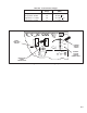
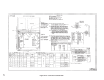
Figure AĆ17. Zero Minimum Speed Correction
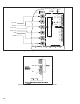
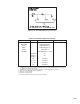
Table AĆ7. Initial/Final Adjustment Settings
Potentiometers Jumpers Initial Setting (Factory) Final Setting (User)
MAX. SPD. Fully CCW (Dot 1)
MIN. SPD Fully CCW (Dot 1)
ACC. Fully CCW (Dot 1)
DEC. Fully CCW (Dot 1)
I LIMIT 150% (Dot 7)
IR COMP Fully CCW (Dot1=0%)
Feedback
1
A
Current
Scaling
2.5
J4
2
Installed
J5, J6
3
Installed
J7, J8
4
Installed
J9
5
Installed
1> AĆCOM is the standard connection for Armature Feedback; Factory Setting.
CĆCOM is the connection for CEMF if CEMF transformer is installed;CEMF function was replaced
by Armature feedback in Design H".
TĆCOM is the connection for Tachometer Feedback if Tach Feedback Kit is installed.
2> Remove if Local Auto/Man Switch is installed.
3> Remove on 230 Volt units.
4> Remove for Torque Taper.
5> Remove when Reverse Relay (Contactor) Kit is installed.