
Hardware Ref, Installation, and Troubleshooting User guide

IV
List of Figures
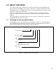
Figure 2.1 Ć Identifying the Drive Model Number 2Ć1.
. . . . . . . . . . . . . . . . . . . . . . . . . . . . . . . . . . . . . . . . . . . . . . .
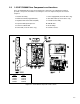
Figure 2.2 Ć 1Ć5 HP Drive Components and Locations 2Ć3.
. . . . . . . . . . . . . . . . . . . . . . . . . . . . . . . . . . . . . . . . . .
Figure 2.3 Ć 7.5Ć10 HP Drive Components and Locations 2Ć4.
. . . . . . . . . . . . . . . . . . . . . . . . . . . . . . . . . . . . . . .
Figure 2.4 Ć 15Ć25 HP Drive Components and Locations 2Ć5.
. . . . . . . . . . . . . . . . . . . . . . . . . . . . . . . . . . . . . . . .
Figure 2.5 Ć 25Ć60 HP Drive Components and Locations 2Ć6.
. . . . . . . . . . . . . . . . . . . . . . . . . . . . . . . . . . . . . . . .
Figure 2.6 Ć 60Ć100 HP Drive Components and Locations 2Ć7.
. . . . . . . . . . . . . . . . . . . . . . . . . . . . . . . . . . . . . . .
Figure 2.7 Ć 100Ć150 HP Drive Components and Locations 2Ć8.
. . . . . . . . . . . . . . . . . . . . . . . . . . . . . . . . . . . . .
Figure 2.8 Ć 1Ć60 HP Regulator Board Components and Locations 2Ć10.
. . . . . . . . . . . . . . . . . . . . . . . . . . . . . . .
Figure 2.9 Ć 60Ć150 HP Regulator Board Components and Locations 2Ć11.
. . . . . . . . . . . . . . . . . . . . . . . . . . . .
Figure 2.10 Ć Jumper J4 Settings for Analog Input Speed Reference 2Ć12.
. . . . . . . . . . . . . . . . . . . . . . . . . . . . .
Figure 2.11 Ć Jumper J17 Settings for Analog Outputs 2Ć13.
. . . . . . . . . . . . . . . . . . . . . . . . . . . . . . . . . . . . . . . . .
Figure 2.12 Ć Typical Terminal Strip Connections 2Ć14.
. . . . . . . . . . . . . . . . . . . . . . . . . . . . . . . . . . . . . . . . . . . . . .
Figure 2.13 Ć Keypad/Display 2Ć15.
. . . . . . . . . . . . . . . . . . . . . . . . . . . . . . . . . . . . . . . . . . . . . . . . . . . . . . . . . . . . . . .
Figure 3.1 Ć Drive Dimensions 3Ć3.
. . . . . . . . . . . . . . . . . . . . . . . . . . . . . . . . . . . . . . . . . . . . . . . . . . . . . . . . . . . . . . .
Figure 3.2 Ć Recommended Air Flow Clearances 3Ć4.
. . . . . . . . . . . . . . . . . . . . . . . . . . . . . . . . . . . . . . . . . . . . . .
Figure 3.3 Ć Single and Multiple Motor Lead Lengths 3Ć7.
. . . . . . . . . . . . . . . . . . . . . . . . . . . . . . . . . . . . . . . . . . .
Figure 4.1 Ć Wire Routing Locations for 1Ć5 HP Drives 4Ć2.
. . . . . . . . . . . . . . . . . . . . . . . . . . . . . . . . . . . . . . . . . .
Figure 4.2 Ć Wire Routing Locations for 7.5Ć10 HP Drives 4Ć3.
. . . . . . . . . . . . . . . . . . . . . . . . . . . . . . . . . . . . . . .
Figure 4.3 Ć Wire Routing Locations for 15Ć25 HP Drives 4Ć4.
. . . . . . . . . . . . . . . . . . . . . . . . . . . . . . . . . . . . . . . .
Figure 4.4 Ć Wire Routing Locations for 25Ć60 HP Drives 4Ć5.
. . . . . . . . . . . . . . . . . . . . . . . . . . . . . . . . . . . . . . . .
Figure 4.5 Ć Wire Routing Locations for 60Ć100 HP Drives 4Ć6.
. . . . . . . . . . . . . . . . . . . . . . . . . . . . . . . . . . . . . . .
Figure 4.6 Ć Wire Routing Locations for 100Ć150 HP Drives 4Ć7.
. . . . . . . . . . . . . . . . . . . . . . . . . . . . . . . . . . . . . .
Figure 5.1 Ć Typical AĆC Input Electrical Connections 5Ć2.
. . . . . . . . . . . . . . . . . . . . . . . . . . . . . . . . . . . . . . . . . . .
Figure 5.2 Ć Typical DĆC Bus Electrical Connections 5Ć3.
. . . . . . . . . . . . . . . . . . . . . . . . . . . . . . . . . . . . . . . . . . . .
Figure 7.1 Ć TwoĆWire Start/Stop Sample Control Wiring 7Ć3.
. . . . . . . . . . . . . . . . . . . . . . . . . . . . . . . . . . . . . . . .
Figure 7.2 Ć ThreeĆWire Start/Stop Sample Control Wiring 7Ć4.
. . . . . . . . . . . . . . . . . . . . . . . . . . . . . . . . . . . . . .
Figure 7.3 Ć Wiring Connections for the Speed Feedback Device 7Ć6.
. . . . . . . . . . . . . . . . . . . . . . . . . . . . . . . .
Figure 9.1 Ć DĆC Bus Voltage Terminals (1Ć25 HP Drives) 9Ć2.
. . . . . . . . . . . . . . . . . . . . . . . . . . . . . . . . . . . . . . .
Figure 9.2 Ć DĆC Bus Voltage Terminals (25Ć60 HP Drives) 9Ć3.
. . . . . . . . . . . . . . . . . . . . . . . . . . . . . . . . . . . . . .
Figure 9.3 Ć DĆC Bus Voltage Terminals (60Ć100 HP Drives) 9Ć4.
. . . . . . . . . . . . . . . . . . . . . . . . . . . . . . . . . . . . .
Figure 9.4 Ć DĆC Bus Voltage Terminals (100Ć150 HP Drives) 9Ć5.
. . . . . . . . . . . . . . . . . . . . . . . . . . . . . . . . . . . .
Figure B.1 Ć Volts/Hertz Regulation Block Diagram BĆ2.
. . . . . . . . . . . . . . . . . . . . . . . . . . . . . . . . . . . . . . . . . . . . .
Figure B.2 Ć Vector Regulation Block Diagram BĆ3.
. . . . . . . . . . . . . . . . . . . . . . . . . . . . . . . . . . . . . . . . . . . . . . . . .