
Hardware Ref, Installation, and Troubleshooting User guide


2Ć13
2.7.1.2 Analog Output Jumper
Jumper
J17 is the analog output jumper
. This jumper selects either a 0Ć10 VDC or 4Ć20 mA scaled
signal output that is programmable for either speed or torque, parameter P
.012. The jumper only
selects a 0Ć10 VDC source voltage or 4Ć20 mA sink current to represent speed or torque. Note that
the 4Ć20 mA current selection requires a power supply for operation as shown in table 7.1, terminals
10 and 11.
Use the following procedure to set jumper J17:
DANGER
DĆC BUS CAPACITORS RETAIN HAZARDOUS VOLTAGES AFTER INPUT POWER HAS BEEN
DISCONNECTED.
AF
TER DISCONNECTING INPUT POWER
, W
AIT FIVE (5) MINUTES FOR THE D
ĆC
BUS CAPACITORS TO DISCHARGE AND THEN CHECK THE VOLTAGE WITH A VOLTMETER TO
ENSURE THE DĆC BUS CAPACITORS ARE DISCHARGED BEFORE TOUCHING ANY INTERNAL
COMPONENTS. FAILURE TO OBSERVE THIS PRECAUTION COULD RESULT IN SEVERE BODILY
INJURY OR LOS
S OF LIFE
.
Step 1. T
urn off input power to the drive and wait five minutes.
Step 2.
Remove the cover from the drive by unscrewing the four attaching screws.
Step 3. V
erify that the D
ĆC bus voltage is zero by following the procedure in section 9.3.
Step 4.
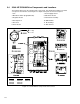
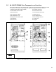
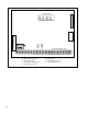
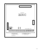
Locate jumper J17 on the Regulator board. Refer to figures 2.8 and 2.9.
Step 5.
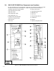
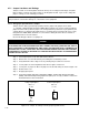
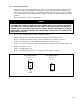
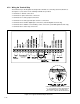
Locate pin 1 on jumper J17. Move the jumper to the desired setting as shown in figure 2.11.
Step 6.
ReĆattach the cover
.
Step 7. ReĆapply input power.
Step 8. V
erify that parameter P
.012 is set correctly for either speed or current.
J17 J17
+10 VDC
Voltage
Output Option
Pins 2Ć3
Current Output Option
Pins 1Ć2
0Ć20 mA
(default)
Figure
2.11 Ć Jumper J17 Settings for Analog Outputs