
Hardware Ref, Installation, and Troubleshooting User guide


3Ć5
3.1.4 Verifying Power Module Input Ratings Match Supplied Power
It
is important to verify that plant power will meet the input power requirements of the GV3000 drive's
P
ower Module circuitry
. Refer to table 2.1 for input power rating specifications. Be sure input power to
the drive corresponds to the drive nameplate voltage and frequency
.
3.2 Wiring Requirements for the Drive
Certain
drive requirements should be checked before continuing with the drive installation. W
ire
sizes, branch circuit protection, speed feedback (for vector regulation), and EĆstop wiring (see
chapter 7), are all areas that need to be evaluated.
3.2.1 Meeting Terminal Strip Input and Output Specifications
The
terminal strip on the Regulator board provides terminals for 24 VDC power for the eight remote
control inputs. Refer to tables A
.3 and A
.4 for control input and output specifications.
3.2.2 Determining Wire Size Requirements
Wire
size should be determined based on the size of conduit openings, NEC/CEC regulations, and
applicable local codes.
DANGER
THE
USER IS RESPONSIBLE FOR CONFORMING WITH ALL APPLICABLE L
OCAL
, NA
TIONAL,
AND
INTERNATIONAL CODES. WIRING PRACTICES, GROUNDING, DISCONNECTS, AND
OVERCURRENT PROTECTION ARE OF PARTICULAR IMPORTANCE. FAILURE TO OBSERVE THIS
PRECAUTION COULD RESULT IN SEVERE BODIL
Y INJURY OR L
OS
S OF LIFE
.
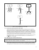
3.2.2.1 Conduit Entry Opening Sizes
It
is important to accurately determine the size of the conduit openings so that the wire planned for a
specific entry point will fit through the opening. Conduit opening sizes are shown in figures 4.1
through 4.6.
3.2.2.2 Recommended
P
ower W
ire Sizes
Input
power wiring should be sized according to applicable codes to handle the drive's
continuousĆrated input current. Output wiring should be sized according to applicable codes to
handle the drive's continuousĆrated output current. See tables 3.3 through 3.7 for recommended
power wire sizes.
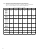
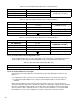
Table 3.3 Ć Recommended P
ower W
ire Sizes for 1Ć10 HP Drives
Type of Wiring Terminals
Size of W
ire (Maximum)
AĆC
Input P
ower R/L1, S/L2, T/L3
Output P
ower U/T1, V/T2, W/T3
12 A
WG, 3 (mm
2
)
D
ĆC Input P
ower +, -
12
A
WG,
3
(mm
)
Table 3.4 Ć Recommended P
ower W
ire Sizes for 15Ć25 HP Drives
Type of Wiring Terminals
Size of W
ire (Maximum)
AĆC
Input P
ower R/L1, S/L2, T/L3
Output P
ower U/T1, V/T2, W/T3
6 AWG, 13 (mm
2
)
D
ĆC Input P
ower +, -
6
AWG,
13
(mm )