
Hardware Ref, Installation, and Troubleshooting User guide


5Ć4
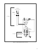
5.3 Installing a Required External/Separate Input Disconnect
An
input disconnect must be installed in the line before the drive input terminals in accordance with
NEC/CEC guidelines. The disconnect should be sized according to the inĆrush current as well as any
additional loads the disconnect might supply
. Note that the trip rating for the inrush current (10Ć12
times full load current) should be coordinated with that of the input isolation transformer
, if used.
Refer to section 5.1 for additional information.
5.4 Installing Power Wiring from the AĆC Input Line to the Drive's Power
Terminals
Use
the following steps to connect AĆC input power to the drive:
Step 1. W
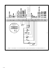
ire the AĆC input power leads by routing them according to drive type. Refer to figures 4.1
through 4.6. T
ables 3.3 through 3.7 contain the recommended power wiring sizes.
On 1Ć5 HP drives, route the power leads through the bottom right opening of the drive base.
On 7.5Ć25 HP drives, route the power leads through the bottom middleĆright opening of the
drive base. If the snubber resistor braking option is used, route the power leads through the
bottom right opening.
On 25Ć60 HP drives, route the power leads through top right or bottom right openings of the
drive base.
On 60Ć100 HP drives, route the power leads through the bottom left opening of the cover
.
On 100Ć150 HP drives, route the power leads through the top left opening of the cover
.
CAUTION: Do not route signal and control wiring with power wiring in the same conduit. This can cause
interference
with drive operation. F
ailure to observe this precaution could result in damage to or destruction
of
the equipment.
Step 2.
Connect the threeĆphase AĆC input power leads (threeĆwire 380Ć460 V
AC) to the proper
terminals according to drive type.
On 1Ć60 HP drives, connect the AĆC input power leads to terminals R/L1, S/L2, T/L3 on the
power terminal strip.
On 60Ć150 HP drives, connect the AĆC input power leads to terminals 1L1, 1L2, and 1L3.
Step 3. T
ighten the AĆC input power terminals to the proper torque as shown in table 5.1.
Table 5.1 Ć T
erminal T
ightening T
orques
Drive
Terminals Maximum Tightening Torque
1Ć25HP All 1.08
NewtonĆmeters (9.5 inĆlbs)
25 60HP
All
13 5 N t t (120 i lb )
25
Ć
60HP
All
13 5 Newton
Ć
meters (120 in
Ć
lbs)
25
Ć
60HP
All
13
.
5
Ne
w
ton
Ć
meters
(120
in
Ć
lbs)
1L1, 1L2, 1L3
UV
W
10 Newton meters (88 5 in lbs)
60Ć100HP
U, V
, W
45,47
10
N
ewtonĆmeters
(
88.5
i
nĆ
lb
s
)
PE,
2.5 NewtonĆmeters (22.1 inĆlbs)
1L1, 1L2, 1L3, PE
10 NewtonĆmeters (88.5 inĆlbs)
100Ć150HP
U, V
, W
, 45, 47
2.5 NewtonĆmeters (22.1 inĆlbs)