
Hardware Ref, Installation, and Troubleshooting User guide


7Ć2
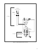
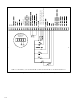
Digital Input Connections (Terminals 16Ć25)
D Terminal
16: +24 VDC (Current Limited) (F
or remote control digital inputs only)
D Terminal 17: Digital Input 8 (Remote/Local) Ć Programmable
D Terminal 18: Digital Input 7 (Ramp1/Ramp2) Ć Programmable
D Terminal 19: Digital Input 6 (F
orward/Reverse) Ć Programmable
D Terminal 20: F
unction Loss
D Terminal 21: Run/Jog
D T
erminal 22: Reset
D Terminal 23: Stop
D T
erminal 24: Start
D Terminal 25: +24 VDC Common
When a user
Ćinstalled function loss input, a coast
ĆtoĆstop pushbutton, or another external interlock is
installed, the factor
Ćinstalled jumper connecting terminals 16 and 20 (or 16A and 20A) must be
removed so that a contact will open to stop the drive.
T
erminals 17, 18, and 19 (remote control inputs 8, 7, and 6) are programmed using parameters P
.007,
P.008, and P.031 through P.038. F
actory default settings are shown here in parentheses. Refer to the
GV3000 Programming Manual (D2Ć3339) for more information.
Snubber Resistor Braking Connections (Terminals 26 and 27)
D Terminal 26: Snubber Resistor Braking Signal (1Ć25HP Drives only)
D Terminal 27: +24 VDC Common
Status Relay Connections (Terminals 28Ć31)
D Terminal
28: N.C Relay Contact
D T
erminal 29: N.C. Relay Common
D Terminal 30: N.O
. Relay Contact
D Terminal 31: N.O
. Relay Common
Relay contact closure is programmable through parameter P
.013. Refer to the GV3000 Programming
Manual (D2Ć3339) for more information.