
Hardware Ref, Installation, and Troubleshooting User guide


7Ć10
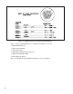
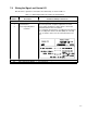
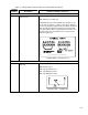
Table 7.1 Ć W
iring Signal and Control I/O to the Terminal Strip (Continued)
Terminal
Number
Description Parameters/Wiring Connections
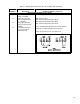
Wiring a Remote/Local Input
16 +24
VDC P
ower Supply
Current limited for remote input logic use only
.
17 Digital Input 8
(Default Ć Remote/Local)
Digital input 8 is control function programmable through
parameter P
.007.
WARNING
IF A MAINTAINED START CONTACT IS USED WHEN THE CONTROL SOURCE = rE,
SWITCHING FROM LOCAL TO REMOTE FROM THE TERMINAL STRIP WILL CAUSE POWER
TO
BE APPLIED TO THE MOTOR IF THE REMOTE ST
ART CONT
ACT IS CL
OSED
. ST
A
Y CLEAR
OF
ROT
A
TING MACHINERY IN THIS CASE
. F
AILURE
TO OB
SERVE THIS PRECA
UTION COULD
RESULT IN BODIL
Y INJURY
.
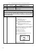
The
following parameters must be set:
P.000:
Control Source
(Only active when P
.000 = rE)
P.006:
Second Menu P
assword
P.007: T
erminal Strip Digital Inputs Configure (Selects
and assigns a control function to digital inputs
6 to 8).
P.008: T
erminal Strip Speed Reference Source
(Analog, Motor Operated P
otentiometer (MOP), or
Preset Speeds)
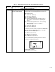
Note that based on the settings of parameters P
.000, P.007,
P.008, and r
.030 if an RMI board is used, the following
parameters can affect digital input 8.
P.023:
MOP Accel/Decel T
ime
P.024:
MOP Reset Configuration
P.031 to P.038: Preset Speeds 1Ć8
Refer to the GV3000 Programming instruction manual
(D2Ć3339) for additional information.
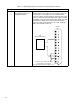
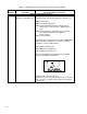
T
erminal 17 On = Local Control
Diagram shows factory setting.