
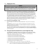
Hardware Ref, Installation, and Troubleshooting User guide


7Ć13
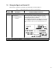
Table 7.1 Ć W
iring Signal and Control I/O to the Terminal Strip (Continued)
Terminal
Number
Description Parameters/Wiring Connections
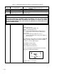
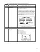
Wiring a Function Loss Input
20 Digital
Input 5
(F
unction Loss)
The following parameters must be set:
P.026: F
unction Loss Response
A signal must be present at terminal 20 for the drive to be
able to start. See figures 7.1 and 7.2. The drive is shipped
from the factory with a jumper between terminals 16 and 20
which provides the signal. The function loss input should
be in series with the drive's external interlocks. In this case,
the jumper must be removed before the connections are
made. See figure 2.12.
Terminal 20 On = No F
unction Loss
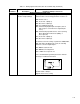
(or from 16A and 20A on 15-60HP drives)
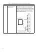
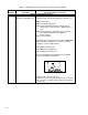
Wiring a Run/Jog Input
21 Digital
Input 4
(Run/Jog)
The following parameters must be set:
P.000:
Control Source
P.020:
Jog Speed Reference
P.021: Jog Ramp Accel Time
P.022:
Jog Ramp Decel T
ime
Terminal 21 On = Jog Operation