
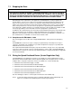
Hardware Ref, Installation, and Troubleshooting User guide


7Ć14
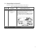
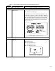
Table 7.1 Ć W
iring Signal and Control I/O to the Terminal Strip (Continued)
Terminal
Number
Description Parameters/Wiring Connections
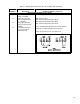
Wiring the Reset Input
22 Digital
Input 3
(Reset)
The following parameter must be set:
P.000:
Control Source
T
erminal 22 On = Reset
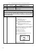
Wiring the Stop/Start Inputs
23
24
Digital
Input 2
(Stop)
Digital Input 1
(Start)
The following parameter must be set:
P.000:
Control Source
P.025:
Stop T
ype
Terminal 23 Off = Stop
Terminal 24 On T
ransition = Start
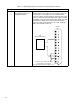
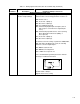
25
24 VDC Isolated Common
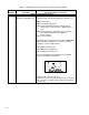
Wiring the Snubber Resistor
26
27
Snubber
Resistor Braking
Control Signal
+24 VDC Isolated Common
Used with Snubber Resistor Braking Kit M/N 2DB4010.
Refer to the kit's instruction manual for installation
instructions.