
Hardware Ref, Installation, and Troubleshooting User guide


9Ć1
9.0 TROUBLESHOOTING THE DRIVE
This
chapter describes how to troubleshoot the drive and the equipment that is needed to do so.
Also provided are replacement part lists and information on clearing faults.
9.1 Test Equipment Needed to Troubleshoot
An
isolated multimeter will be needed to measure DĆC bus voltage and to make resistance checks.
9.2 Drive Alarms and Faults
The
drive will display alarm and fault codes to assist in troubleshooting when a problem develops
during self
Ćtuning or drive operation.
If an alarm condition occurs, the drive will continue to run and a 2Ć or 3Ćdigit alarm code will flash on
the display.
If a fault occurs, the drive will coast
ĆtoĆstop and a 2Ć or 3Ćdigit fault code will flash on the display.
Refer to the GV3000 Software Start
ĆUp and Reference Manual (D2Ć3339) for more information on
drive alarms and faults.
9.3 Verifying That DĆC Bus Capacitors are Discharged
DANGER
DĆC BUS CAPACITORS RETAIN HAZARDOUS VOLTAGES AFTER INPUT POWER HAS BEEN
DISCONNECTED.
AF
TER DISCONNECTING INPUT POWER
, W
AIT FIVE (5) MINUTES FOR THE D
ĆC
BUS CAPACITORS TO DISCHARGE AND THEN CHECK THE VOLTAGE WITH A VOLTMETER TO
ENSURE THE DĆC BUS CAPACITORS ARE DISCHARGED BEFORE TOUCHING ANY INTERNAL
COMPONENTS. FAILURE TO OBSERVE THIS PRECAUTION COULD RESULT IN SEVERE BODILY
INJURY OR LOS
S OF LIFE
.
The GV3000 drive's D
ĆC bus capacitors retain hazardous voltages after input power has been
disconnected. P
erform the following steps before touching any internal components:
Step 1. T
urn off and lock out input power. W
ait five minutes.
Step 2.
Remove the drive's cover
.
Step 3. V
erify that there is no voltage at the drive's input power terminals.
Step 4.
Measure the D
ĆC bus potential with a voltmeter
.
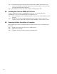
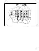
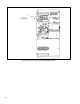
F
or 1Ć60 HP drives, measure the D
ĆC bus potential at the DĆC bus power terminals. See
figures 9.1 and 9.2.
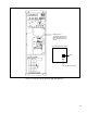
F
or 60Ć100HP drives, while standing on a nonĆconductive surface and wearing insulated
gloves (600V), remove the top two screws of the regulator panel and tilt the panel forward.
See figure 9.3. Measure the D
ĆC bus potential at the diode bridge as shown. ReĆattach the
regulator panel.