
Hardware Ref, Installation, and Troubleshooting User guide


9Ć2
F
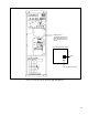
or 100Ć150HP drives, while standing on a nonĆconductive surface and wearing insulated
gloves (600V), remove the top two screws of the regulator panel and tilt the panel forward.
See figure 9.4. Measure the D
ĆC bus potential at the bottom of the fuse holders on the
P
ower Module Interface board on the back of the regulator panel. T
ake care not to touch
any conductive traces. ReĆattach the regulator panel.
Step 5.
Once the drive has been serviced, reĆattach the drive's cover
.
Step 6. ReĆapply input power.
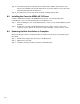
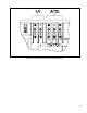
Figure 9.1 Ć DĆC Bus V
oltage T
erminals (1Ć25 HP Drives)