
Hardware Ref, Installation, and Troubleshooting User guide


9Ć6
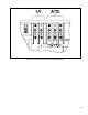
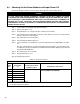
9.4 Checking Out the Power Modules with Input Power Off
Use
the following procedure to check the drive's P
ower Module circuitry with power off:
DANGER
DĆC BUS CAPACITORS RETAIN HAZARDOUS VOLTAGES AFTER INPUT POWER HAS BEEN
DISCONNECTED.
AF
TER DISCONNECTING INPUT POWER
, W
AIT FIVE (5) MINUTES FOR THE D
ĆC
BUS CAPACITORS TO DISCHARGE AND THEN CHECK THE VOLTAGE WITH A VOLTMETER TO
ENSURE THE DĆC BUS CAPACITORS ARE DISCHARGED BEFORE TOUCHING ANY INTERNAL
COMPONENTS. FAILURE TO OBSERVE THIS PRECAUTION COULD RESULT IN SEVERE BODILY
INJURY OR LOS
S OF LIFE
.
Step 1. T
urn off and lock out input power. W
ait five minutes.
Step 2.
Remove the drive's cover
.
Step 3. V
erify that there is no voltage at the drive's input power terminals.
Step 4.
Check the D
ĆC bus potential with a voltmeter as described in section 9.3 to ensure that the
D
ĆC bus capacitors are discharged.
Step 5.
Disconnect the motor from the drive.
Step 6.
Check all AĆC line and D
ĆC bus fuses.
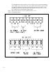
Step 7.
If a fuse is blown, use a multimeter to check the input diodes and output IGBT
s. See table
9.1.
Note that 1Ć10HP drives do not have replaceable transistor modules: the entire drive must
be replaced if a transistor malfunctions. Intelligent P
ower Modules (IPM) may be replaced if
they fail in a 60Ć150HP drive.
Step 8.
ReĆconnect the motor to the drive.
Step 9.
ReĆattach the drive's cover
.
Step 10. ReĆapply input power.
T
able 9.1 Ć Resistance Checks
1Ć60HP Drives
Input
Diode
No.
Meter
Connection
(+) (-)
Component is OK if
resistance (R) is:
Component is defective if:
1 ă* R/L1
50 < R < 10 Megohm
Continuity (short circuit) or open when the meter is
connected with reversed polarity
2 ă* S/L2
connected with reversed polarity
3 ă* T/L3
4 R/L1 **
5 S/L2 **
6 T/L3 **
* (+) D
ĆC Bus V
olts power terminal
** (-) D
ĆC Bus V
olts power terminal