
User Manual


Troubleshooting the Drive
9-17
* Components are identified in figure 2.8.
** Three sets of two IGBTs (P/N 602909–808AW) for a 200 HP drive.
*** Three sets of four IGBTs (P/N 602909–808AW) for 250–400 HP drives, inclusive.
**** Ten DC bus capacitors in a 200 HP drive. Eighteen DC bus capacitors in 250-400 HP drives, inclusive.
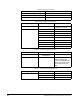
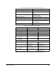
***** When replacing PMI boards, you must set rotary switches SW1, SW2, and SW3 based on the drive’s
horsepower rating as shown below. All three switches are set to the same position.
Drive HP Switch
Rating
Position
200 0
250 1
300 3
350 7
400 F
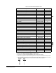
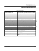
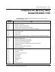
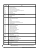
Table 9.8 – 200-400 HP Drive Replacement Parts
Description* Part Number Quantity
Phase Module Assembly 807300–124R 3***
Phase Module Assembly 807300–158R 3**
SCR Module Assembly 807300–200R 1
Blower Motor 616300–100R 1
Blower Starter Capacitor 69932–24QK 1
Fault Thermostat 66012–16B 4
Gate Driver PCB 0–56956 3
DC Bus Capacitor 600442–34SU 10/18****
SCR Diode 701819–207BA 3
Bus Control PCB 0–56966 1
Bus Control PCB Fuse 64676–65B 6
Disconnect Switch 65242–11A 1
AC Input Fuse 64676–120BDX 3
Blower Fuse 64676–64G 2
Blower Transformer 411027–130A 1
Regulator PCB 0–56940–6xx 1
Power Module Interface PCB***** 0–56942 1
Current Feedback Sensor 600595–18A 3
Blower Filter 69470–10H 1
Ground Fault Current Transformer 64670–43A 1
DC Bus Discharge Resistor 616300–117R 3
Keypad 410483–15A 1
SCR Gate Wiring Harness 807300–141S 1
Gate Driver/Power Supply Wiring Harness 807300–139S 1
Raceway Wiring Harness 807300–156R 1
LPI/LEM Wiring Harness 807300–137R 1
Blower Fuses to Bus Bar Wiring Harness 616300–137R 1
Transformer/Fuses Wiring Harness 616300–136R 1
Transformer/Terminal Block Wiring Harness 616300–135R 1