
User Manual

Compliance with Electromagnetic Compatibility Standards
C-9
C.4.1 Connecting the AC Mains Filter Output to the GV3000/SE Drive
Input
The following sections describe how to wire the AC Mains Filters to the GV3000/SE
drives.
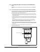
C.4.1.1 Connecting AC Mains Filters M/N 2DF4283, 2DF4284, 2DF4285, and 2DF4286
The power leads that connect the output terminals of the AC Mains Filter to the drive’s
AC input terminals are included with the filter. The flexible conduit to be used with
these power leads is also provided. See figure C.5.
•
Place the flexible conduit’s hub in the drive’s wire entry hole that is in-line with the
filter’s output wiring opening. Route the leads through the conduit. Secure both ends
of the flexible conduit.
•
Trim the power leads to the proper length and connect them to the drive’s AC input
power terminals (R,S,T). Connect the green/yellow ground lead to the drive’s ground
terminal.
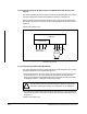
Note that the filter’s output leads are red, yellow, and blue. This color coding is
stenciled on the printed circuit board at the filter’s input power terminals to help
identify the filter’s output wiring relative to the filter’s input wiring.
•
When the drive is connected to three-phase AC input power, the three output leads
from the filter should be connected to the drive’s AC input power terminals as shown
in figure C.5.
•
Connect the filter ground wire (green/yellow) to the drive ground.
Continue with section C.4.2.
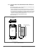
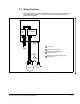
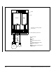
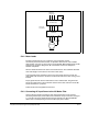
Figure C.5 – Typical Three-Phase Connections for AC Mains Filters
M/N 2DF4283, 2DF4284, 2DF4285, and 2DF4286
R/L1 S/L2 T/L3 GND
U/T1 V/T2 W/T3 GND
GV3000/SE
LL L
E(GND)
RED
YELLOW BLUE YELLOW
AC Mains Filter
GREEN/
AB
12 3
MOTOR
C
FILTER'S AC INPUT POWER
DRIVE'S AC INPUT POWER