
User Manual


About the Drive
2-19
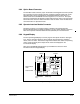
2.8.4 Option Board Connector
The flat-ribbon cable connector (J3) on the left side of the Regulator board is a parallel
bus connection port that provides a means of attaching optional boards such as the
DeviceNet Option board, the RMI board, the AutoMax Network Option board, or
similar boards to the GV3000/SE drive. See figures 2.9, 2.10, and 2.11. The option
board is mounted below the Regulator board inside the drive. Refer to the appropriate
board instruction manual for more information. Refer to section 2.9 of this manual for
more information on optional drive kits.
2.8.5 Operator Interface Module Connector
Flat-ribbon connector J7 provides a means of attaching the optional Operator
Interface Module (OIM). The OIM is available for use as a remote keypad for the drive.
Refer to the Operator Interface Module manual (D2-3342) for more information.
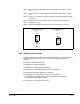
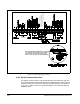
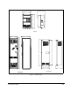
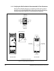
2.8.6 Keypad/Display
The front panel keypad/display is used to program and operate the drive. See figure
2.15. The four-character display is used to indicate drive parameters, parameter
values, and error codes. The fourteen single LEDs indicate drive status and operating
mode, as well as identify drive outputs whose values are displayed on the
four-character display.
Refer to the GV3000/SE Software Start-Up and Reference manual for more
information about the keypad/display.
Figure 2.15 – Keypad/Display
!
Forward
Reverse
AUTO
MAN
ENTER
RUN
JOG
PROGRAM
START
STOP
RESET
SPEED
VOLTS
AMPS
Hz
Kw
TORQUE
Password
RUNNING
REMOTE
JOG
AUTO
FORWARD
REVERSE
PROGRAM
RELIANCE
ELECTRIC
Keypad
STOP/RESET
START Key
Display
Key
Drive Status LEDs
Monitor Mode
LEDs
Password LED