
User Manual

7-4
GV3000/SE AC Drive Hardware Reference, Version 6.06
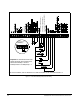
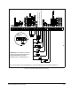
Figure 7.1 – Two-Wire Start/Stop Sample Control Wiring
*FOR 15-60 HP DRIVES, USE 16A INSTEAD OF 16 AND 20A INSTEAD OF 20. ALSO SEE FIGURE 2.14.
PHASE B NOT
DIGITAL INPUT 8 (REMOTE/LOCAL)
DIGITAL INPUT 7 (RAMP1/RAMP 2)
DIGITAL INPUT 6 (FORWARD/REVERSE)
PHASE B
Remote 4-20 mA
Speed/Torque
Reference
Important: A maintained function loss
switch should be used if P.054 (Level
Sense Start Enable) = ON and
P.026 (Function Loss Response) = 1.