
User Manual
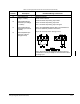

Wiring the Regulator Board Terminal Strip
7-7
7.2 Wiring the Encoder Feedback Device
(FVC Regulation Only)
If the GV3000/SE drive is programmed to provide FVC regulation, an encoder must be
installed. Drives using V/Hz or SVC regulation do not require the use of an encoder
feedback device. The encoder connects to terminals 4 through 9 of the Regulator
board terminal strip as shown in table 7.8.
Use the following procedure to connect an encoder to the Regulator board’s terminal
strip:
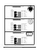
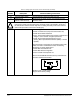
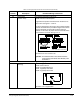
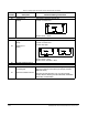
Step 1. Connect the encoder’s wires to terminals 4 through 9 of the terminal strip.
See figure 7.3. See table A.6 for additional encoder specifications. Refer to
section 3.2.4.1 for encoder wiring guidelines.
Step 2. Set the following parameters to establish the maximum motor speed:
•
P.004: Maximum Speed
•
U.001: Encoder PPR
•
U.002: Motor Poles
•
U.003: Motor Nameplate Base Frequency
•
U.005: Motor Nameplate RPM
•
U.017: Motor Top Speed
Refer to the GV3000/SE Software Start-Up and Reference manual for parameter
descriptions.
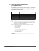
Table 7.8 – Encoder Connections
Terminal Encoder Connection
4 Encoder Supply +15 VDC (250 mA capacity)
5 Encoder Phase A Differential Input
6 Encoder Phase A Not Differential Input
7 Encoder Phase B Differential Input
8 Encoder Phase B Not Differential Input
9 Encoder/Regulator Common