Quick Start Logix5000 Control Systems: Connect POINT I/O Modules over a DeviceNet Network Catalog Numbers Logix5000 Controllers, 1734 POINT I/O Modules
Important User Information Solid-state equipment has operational characteristics differing from those of electromechanical equipment. Safety Guidelines for the Application, Installation and Maintenance of Solid State Controls (publication SGI-1.1 available from your local Rockwell Automation sales office or online at http://www.rockwellautomation.com/literature/) describes some important differences between solid-state equipment and hard-wired electromechanical devices.
Table of Contents Preface About This Publication . . . . . . . . . . . . . . . . . . . . . . . . . . . . . . . . . . . . . . . . . . . . 5 Before Using This Publication. . . . . . . . . . . . . . . . . . . . . . . . . . . . . . . . . . . . . . 5 Other Logix5000 Control System Quick Starts . . . . . . . . . . . . . . . . . . . . . . 8 Where to Start . . . . . . . . . . . . . . . . . . . . . . . . . . . . . . . . . . . . . . . . . . . . . . . . . . . . 9 How Hardware is Connected . . . . . . . . . . . . . .
Table of Contents Notes: 4 Rockwell Automation Publication IASIMP-QS026A-EN-P - July 2012
Preface About This Publication This quick start provides examples and procedures for including POINT I/O modules in a Logix5000 controllers control system over a DeviceNet network. The programming examples are not complex, and offer easy solutions to verify that devices are functioning and communicating properly. IMPORTANT This publication describes example tasks you complete when using POINT I/O modules on a DeviceNet network.
Preface This table describes the tasks you must complete before using this publication. Table 1 - Required Tasks To Complete Before Using this Quick Start Task Description Prepare the Logix5000 Assembling the control system and connecting to the DeviceNet network. At minimum, your system must control system include a controller, DeviceNet scanner module to access the DeviceNet network and the components required hardware to install a DeviceNet network.
Preface Table 1 - Required Tasks To Complete Before Using this Quick Start Task Description Configure the network Complete tasks associated with configuring the DeviceNet network with RSNetWorx for DeviceNet software, such setting the node address for the DeviceNet scanner module your controller uses to access the DeviceNet network.
Preface Other Logix5000 Control System Quick Starts This quick start describes how to use a single component-type over a single network in a Logix5000 control system. Typically, though, a Logix5000 control system includes more than the controller, communication module and a single component over a single network. For example, if a Logix5000 control system operates on a DeviceNet network, the system might use remote I/O modules, HMI devices and drives in addition to the controller and communication modules.
Preface Where to Start Required Tasks Described in the appropriate Logix5000 controller quick start 1. Prepare the Controller Hardware 2. Prepare the Computer 3. Configure the Network 4.
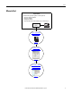
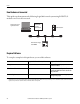
Preface How Hardware is Connected This quick start demonstrates the following Logix5000 control system using POINT I/O modules on a DeviceNet network.
Preface Parts List You need these parts to use this publication. Quantity Cat. No.
Preface Additional Resources Use the additional resources listed in this table for more information when using POINT I/O modules over a DeviceNet network in a Logix5000 controller project. Resource Description POINT I/O DeviceNet Adapter Installation Instructions, publication 1734-IN026 Describes the installation of the adapter and technical specifications.
Chapter 1 Prepare the Distributed POINT I/O Hardware In this chapter, you learn how to complete the following tasks: • Install the 1734-ADN DeviceNet adapter • Install the 1734-OB4E digital output module • Install the 1794-PS3 FLEX I/O power supply • Connect power to the 1734-ADN DeviceNet adapter Before You Begin Before you begin, complete these tasks described in Before Using This Publication on page 5: • Prepare the Logix5000 control system hardware - Verify the control system and DeviceNet network
Chapter 1 Prepare the Distributed POINT I/O Hardware What You Need This table lists what products you need to complete the tasks described in this chapter. Quantity Cat. No.
Prepare the Distributed POINT I/O Hardware Chapter 1 Mount and Connect the 1734-ADN DeviceNet Adapter Complete the following tasks to mount and connect the 1734-ADN DeviceNet adapter. 1. Press the adapter onto the DIN rail. 2. Set the network node address with the thumbwheel switch. This quick start uses node 02. Module Status Switches 02 PointBus Status ControlNet A Status ControlNet B Status 1734-ACNR 3. If the DeviceNet connector is installed on the 1734-ADN adapter module, remove it.
Chapter 1 Prepare the Distributed POINT I/O Hardware 4. Connect the 1799-DNC5MMS 5pin linear to micro male adapter to the female end of the 1485K-P1F5R5 KwikLink right-angle micro male to micro female connector cable. 5. Connect the female end of the DeviceNet cable to the adapter. Adapter Status DeviceNet Status PointBus Status 1734-ADN System Power Field Power 6. Connect the other end of the cordset to the DeviceNet network. 7. Remove the safety end cap.
Prepare the Distributed POINT I/O Hardware Chapter 1 Mount the 1734-OB4E Digital Output Module 1. Install the removable terminal base (RTB) on the mounting base; making sure the handle is in the down position. 2. Using a small screwdriver, rotate the keyswitch on the mounting base to match the position on the keyswitch on the 1734-OB4E module. This example shows the keyswitch in position 1. Handle Keyswitch Mounting Base Removable Terminal Block 3. Press the 1734-OB4E module into the wiring base.
Chapter 1 Prepare the Distributed POINT I/O Hardware Mount and Wire the 1794-PS3 Power Supply Use a 1794 FLEX I/O power supply to power the distributed POINT I/O modules. This publication uses the 1794-PS3 power supply. WARNING: Verify that all incoming power is turned off before wiring power. 1794-PS3 Power Supply 1. Hook the upper-lip of the DIN rail latch onto the DIN rail. Upper-lip of DIN rail latch. 2. Press the module onto the DIN rail. 3.
Prepare the Distributed POINT I/O Hardware Chapter 1 Wire the 1734-ADN DeviceNet Adapter to the Power Supply 1. Connect the 12/24V DC common and 12/24V DC power wires from the power supply to the adapter. Adapter Status DeviceNet Status Module Status Network Status NODE: PointBus Status 1734-ADN 2. Turn on incoming power.
Chapter 1 Prepare the Distributed POINT I/O Hardware Notes: 20 Rockwell Automation Publication IASIMP-QS026A-EN-P - July 2012
Chapter 2 Create DeviceNet Network Software Files In this chapter, you complete the following tasks: • Register an EDS file in RSNetWorx for DeviceNet software • Set the DeviceNet scanner module’s node address • Create a DeviceNet configuration file • Change the POINT I/O DeviceNet network adapter’s configuration • Change the DeviceNet network configuration IMPORTANT Multiple Logix5000 control systems can use POINT I/O modules over a DeviceNet network.
Chapter 3 Create DeviceNet Network Software Files Before You Begin Before you begin, you must complete these tasks: • These tasks described in Before Using This Publication on page 5: – Prepare the Logix5000 control system hardware – Prepare the computer – Configure the network – Create an RSLogix 5000 project • These tasks described in Chapter 1, Prepare the Distributed POINT I/O Hardware on page 13: – – – – Mount and Connect the 1734-ADN DeviceNet Adapter Mount the 1734-OB4E Digital Output Module Moun
Create DeviceNet Network Software Files Chapter 3 Follow These Steps Register an EDS File - Optional page 24 Set the 1769-SDN Scanner Module’s Node Address page 27 Create a DeviceNet Configuration File page 30 Edit the DeviceNet Adapter Paramete rs page 34 Configure the DeviceNet Subnet page 36 Create a DeviceNet Scanlist page 41 Rockwell Automation Publication IASIMP-QS026A-EN-P - July 2012 23
Chapter 3 Create DeviceNet Network Software Files Register an EDS File - Optional You might need to register a device for use in RSNetWorx for DeviceNet software so the software recognizes the device and uses it appropriately. You register an electronic data sheet (EDS) file in the software. If you do not need to register an EDS file in RSNetWorx for DeviceNet software, skip to Set the 1769-SDN Scanner Module’s Node Address on page 27. 1.
Create DeviceNet Network Software Files Chapter 3 6. When the EDS dialog box appears, click Next. 7. Verify that Register an EDS file(s). is checked and click Next. 8. Browse to the EDS file and click Next.
Chapter 3 Create DeviceNet Network Software Files 9. When the EDS File Installation Test Results screen appears, click Next. 10. Select the graph image for the device you want to register and click Next. 11. Select the device you want to register and click Next. 12. Click Finish when the registration is successful.
Create DeviceNet Network Software Files Chapter 3 Set the 1769-SDN Scanner Module’s Node Address IMPORTANT The tasks described in this section require the use of the Node Commissioning tool in RSNetWorx for DeviceNet software. If you are using RSLogix 5000 software, version 20 or later, as required with this quick start, the Node Commissioning tool was an optional choice during the software installation. If you did not install the Node Commissioning tool previously, do so now.
Chapter 3 Create DeviceNet Network Software Files 4. Click Browse. When the Device Selection dialog box appears, you can browse to the 1769-SDN scanner module over an EtherNet/IP network or USB connection. This example uses an EtherNet/IP network connection. 5. Under the AB_ETHIP-1 driver, expand the path to the 1769-SDN scanner module as shown in the example graphic. 6. Click OK. 7. If you receive a linking device warning, click Yes.
Create DeviceNet Network Software Files Chapter 3 8. Enter a node address of 1 for the 1769-SDN scanner module and click Apply. The Address is applied and is confirmed in the Messages box. 9. Record the node address. 10. Click Close.
Chapter 3 Create DeviceNet Network Software Files Create a DeviceNet Configuration File 1. From the File pull-down menu, choose New. 2. Click Who Active to go online. 3. Expand the networks to the appropriate DeviceNet network. In this example, the network is Port 2, DeviceNet.
Create DeviceNet Network Software Files 4. Record the following information about the 1769-SDN scanner module: • • Chapter 3 Slot number = 1 DeviceNet network node number = 1 Slot number in the CompactBus = 1 DeviceNet network node number = 1 5. Click OK. 6. Click OK when the alert about uploading or downloading device information. RSNetWorx for DeviceNet software browses the network and shows the scanner module at DeviceNet network node number 1 and the 1734-ADN adapter at node number 2.
Chapter 3 Create DeviceNet Network Software Files 7. Right-click the 1769-SDN scanner module and choose Properties. 8. Click the Module tab. 9. Click Download. All configuration is cleared from the 1769-SDN scanner module, and the software is synchronized with the module.
Create DeviceNet Network Software Files Chapter 3 10. From the Platform pull-down menu, choose CompactLogix. 11. Enter the slot number of the 1769-SDN scanner module. 12. Click OK. 13. Save the file and record the file name and path. This quick start uses the example file name DeviceNet.dnt.
Chapter 3 Create DeviceNet Network Software Files Edit the DeviceNet Adapter Parameters Complete the following steps to edit the 1734-ADN adapter’s configuration parameters. 1. Right-click the adapter and choose Properties. 2. Click the Parameters tab. 3. When prompted to upload or download configuration, click Upload.
Create DeviceNet Network Software Files Chapter 3 4. Change the following parameters: • • AutoAddress Backplane Modules= 1 Auto Start Mode = Map Data to DWord Boundaries. 5. Click Apply. 6. When prompted to update the adapter’s configuration, click Yes. 7. Click OK. 8. Save the DeviceNet configuration file.
Chapter 3 Create DeviceNet Network Software Files Configure the DeviceNet Subnet 1. From the File pull-down menu, choose New. 2. Click Who Active to go online. 3. Expand the appropriate network and select the DeviceNet Subnet, DeviceNet network. 4. Click OK. 5. Click OK to upload device information.
Create DeviceNet Network Software Files Chapter 3 The modules on the subnet appear. 6. From the Network pull-down menu, choose Upload from Network. 7. When prompted to upload entire network, click Yes. 8. Right-click the 1734-ADN adapter and choose Properties. The remaining steps will associate a main and subnet .dnt project for the 1734-ADN module so you can easily switch between the two projects in RSNetWorx for DeviceNet software. You also need the main and subnet .
Chapter 3 Create DeviceNet Network Software Files 9. On the Device Bridging tab, click Associate File. 10. Select the main DeviceNet configuration file and click Open. 11. When the updated 1734-ADN Point I/O Scanner dialog box appears, click OK.
Create DeviceNet Network Software Files Chapter 3 12. Save the DeviceNet subnet configuration file. Name the file so it can be easily identified as the subnet. This quick start uses the name SubnetDeviceNet.dnt. 13. Record the file name. 14. From the File menu, choose Open. 15. Select the main DeviceNet file and click Open.
Chapter 3 Create DeviceNet Network Software Files 16. Right-click the 1734-ADN adapter and choose Properties. 17. On the Device Bridging tab, click Associate File. 18. Select the subnet configuration file and click Open.
Create DeviceNet Network Software Files Chapter 3 19. When the updated 1734-ADN Point I/O DeviceNet Adapter dialog box appears, click OK. 20. Click OK. 21. Save your main DeviceNet configuration file. Create a DeviceNet Scanlist 1. Verify that the network is online. 2. If the network is not online, choose Online from the Network pull-down menu. 3. When alerted to uploading or downloading device information, click OK. 4. From the Network pull-down menu, choose Upload from Network.
Chapter 3 Create DeviceNet Network Software Files 5. When prompted to upload entire network, click Yes. 6. Right-click the 1734-ADN adapter and choose Properties. 7. Click the Parameters tab and record the parameters shown. 8. Click OK.
Create DeviceNet Network Software Files Chapter 3 9. Right-click the 1769-SDN scanner module and choose Properties. 10. On the Scanlist tab, click Upload from Scanner. The configuration is uploaded from the device. 11. On the Upload Scanlist from Scanner dialog box, check All Records and click Upload 12. Click Upload.
Chapter 3 Create DeviceNet Network Software Files 13. Select the 1734-ADN adapter and move it to the Scanlist. 14. Click Edit I/O Parameters. 15. Verify that the I/O parameters match step 7 on page 42; if not, update them. 16. Click OK. 17. Verify that Automap on Add is checked and click Apply.
Create DeviceNet Network Software Files Chapter 3 18. When prompted to download changes, click Yes. 19. Click OK to close the 1769-SDN Scanner Module dialog box. 20. Save the configuration file. 21. Close RSNetworx for DeviceNet software.
Chapter 3 Create DeviceNet Network Software Files Notes: 46 Rockwell Automation Publication IASIMP-QS026A-EN-P - July 2012
Chapter 3 Use the POINT I/O Adapter and Output Module in an RSLogix 5000 Project In this chapter, you complete the following tasks: • Create DeviceNet tags with the DeviceNet Tag Generator tool • Add ladder logic to the RSLogix 5000 project • Download the updated project to your controller • Test the ladder logic on your 1734-OB4E output module IMPORTANT Multiple Logix5000 control systems can use POINT I/O modules over a DeviceNet network.
Chapter 3 • These tasks described in Chapter 1, Prepare the Distributed POINT I/O Hardware on page 13: – – – – • Use the POINT I/O Adapter and Output Module in an RSLogix 5000 Project Mount and Connect the 1734-ADN DeviceNet Adapter Mount the 1734-OB4E Digital Output Module Mount and Wire the 1794-PS3 Power Supply Wire the 1734-ADN DeviceNet Adapter to the Power Supply These tasks described in Chapter 2, Create DeviceNet Network Software Files on page 21: – – – – – Set the 1769-SDN Scanner Module’s N
Use the POINT I/O Adapter and Output Module in an RSLogix 5000 Project Chapter 3 Follow These Steps Create DeviceNet Tags page 50 Add Ladder Logic page 53 Download the Project page 56 Test the 1734-OB4E Digital Output Module’s Tags page 57 Rockwell Automation Publication IASIMP-QS026A-EN-P - July 2012 49
Chapter 3 Use the POINT I/O Adapter and Output Module in an RSLogix 5000 Project Create DeviceNet Tags IMPORTANT Before running the DeviceNet Tag Generator, verify the following: • RSLogix 5000 software is running and the project is open. • RSNetWorx for DeviceNet software is closed. 1. Launch the DeviceNet Tag Generator. 2. Select your RSLogix 5000 project and click Select Scanner. 3.
Use the POINT I/O Adapter and Output Module in an RSLogix 5000 Project Chapter 3 4. Select the main DeviceNet configuration file and click Select Scanner Node. 5. Select the node of the DeviceNet scanner module and click Generate Tags. 6. Click Generate Tags.
Chapter 3 Use the POINT I/O Adapter and Output Module in an RSLogix 5000 Project 7. When prompted to continue, click Yes. When tag generation is complete, the text log appears. 8. Close the DeviceNet Tag Generator. The DeviceNet Tag Generator created new programs and tags that were added to the controller organizer in your RSLogix 5000 project.
Use the POINT I/O Adapter and Output Module in an RSLogix 5000 Project Chapter 3 Add Ladder Logic 1. In RSLogix 5000 software’s controller organizer, expand Tasks >MainTask>MainProgram. 2. Double-click MainRoutine. A blank routine opens. 3. Add a new rung to the routine. 4. From the Element Toolbar, drag and drop an Examine On element and an Output Energize element onto the rung. 5. Double-click the ? in the Examine On element. 6. Type PB for push button. 7. Press Enter.
Chapter 3 Use the POINT I/O Adapter and Output Module in an RSLogix 5000 Project 8. Right-click PB and choose New “PB”. 9. When the New Tag dialog box appears, click Create and Close to use the default values. 10. Double-click the ? in the Output Energize element. 11. Name the Output Energize element OB4E_Light. IMPORTANT Do not use spaces in the tag name. Use underscores (__) instead. 12. Right-click the OB4E_Light tag and choose New ‘OB4E_Light’.
Use the POINT I/O Adapter and Output Module in an RSLogix 5000 Project Chapter 3 13. From the Type pull-down menu, choose Alias. 14. From the Alias For pull-down menu, browse to the 1734-OB4E digital output module and choose the bit for the light you want to turn on. This example uses Local_DeviceNet_scanner_N02_S 01_COS_O.Data_0. 15. Click Create and Close. This graphic shows the rung with each element configured.
Chapter 3 Use the POINT I/O Adapter and Output Module in an RSLogix 5000 Project Download the Project 1. Save your changes. 2. Move the controller’s mode switch to the PROG position. RUN REM PROG 3. Click the Controller Status icon and choose Download. 4. In the Who Active dialog box, choose your controller and click Download. 5. Click Download one more time.
Use the POINT I/O Adapter and Output Module in an RSLogix 5000 Project Chapter 3 Test the 1734-OB4E Digital Output Module’s Tags 1. Move the controller’s mode switch to the RUN position. RUN REM PROG 2. In the configuration tree, doubleclick Controller Tags. 3. Change the O.CommandRegister.Run tag to 1. The 1769-SDN scanner module transitions to Run mode.
Chapter 3 Use the POINT I/O Adapter and Output Module in an RSLogix 5000 Project 4. If not open, open the project’s Main Routine to find the ladder logic written earlier in this chapter. 5. Select the PB and press Ctrl+T. This toggles the state from 0 to 1 (off to on). 6. Verify that the light on the distributed digital output module turns on. 7. Press Ctrl+T to toggle the state back to 0 (off ). 8. Go Offline.
Index Numerics 1485K-P1F5-R5 KwikLink right-angle micro male to micro female connector cable 11, 14 1485P-P1E4-R5 KwikLink sealed micro connector 11, 14 1734-ADN adapter 11, 14 1734-OB4E output module 11, 14 1734-RTB removable terminal block 11, 14 1734-TB mounting base 11, 14 1769-SDN scanner module 27-29 1785K-P1F5-R5 KwikLink right-angle micro male to micro female connector cable 11, 14 1785P-P1E4-R5 KwikLink sealed micro connector 11, 14 1794-PS3 power supply 11, 14 mount 18 1799-DNC5MMS 5-pin linear to
Index L ladder logic use to test 1734-OB4E output module 53-58 Logix5000 controllers prerequisite tasks 6-7 quick starts 8 M mount 1734-ADN adapter 15-16 1734-OB4E output module 17 1794-PS3 power supply 18 RSLogix 5000 software 7 add DeviceNet adapter and output module 47-58 add ladder logic 53-58 requirements 10 use DeviceNet Tag Generator 50-52 RSNetWorx for DeviceNet software 7, 21-45 configuration file 30-33 configure network subnet 36-41 configure scanlist 41-45 edit 1734-ADN adapter parameters 34-3
Rockwell Automation Support Rockwell Automation provides technical information on the Web to assist you in using its products. At http://www.rockwellautomation.com/support/, you can find technical manuals, a knowledge base of FAQs, technical and application notes, sample code and links to software service packs, and a MySupport feature that you can customize to make the best use of these tools.