
User guide


Using Multi-Drive Mode
8-7
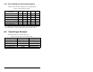
Important: MDCOMM-ENET parameters can be set using MDI
peripheral (OIM) ONLY when the Operating Mode
Switch is in the Single
8.5 Example Multi-Drive Ladder Logic
Program
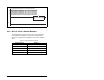
The ladder logic program example demonstrates using Multi-Drive
mode with five drives. See figure 8.2 for a system layout diagram.
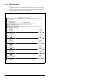
8.5.1 Function of Example Program
The example program provided is for the ControlLogix, but other
controllers can also be used. This example program enables you to:
• View status information from the drives such as Ready, Fault, At
Speed, and Feedback.
• Control the drives using various Logic Command bits (Stop, Start,
etc.) and Reference.
• Perform a single parameter read and write for each drive. The
example uses drive parameter 39 (Accel Time) for both so you
can see (read) the change after a write is performed.
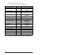
8.5.2 Module Settings for the Example Program
• The Operating Mode Switch (SW1) on the module is set to the
Multi-Drive operation position. Table 8.4 shows the module
parameter settings.
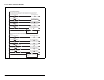
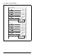
Table 8.4 – Module Parameter Settings
Parameter Value Description
22 (MDI I/O Cfg) 4 “Drives 0-4” - 5 drives on 1 node
24 (Drv 0 Addr)
1
1
The settings for these parameters must match the Parameter A104
(Comm Node Addr) settings in the respective drives.
1 Modbus address of Drive 0
25 (Drv 1 Addr)
1
2 Modbus address of Drive 1
26 (Drv 2 Addr)
1
3 Modbus address of Drive 2
27 (Drv 3 Addr)
1
4 Modbus address of Drive 3
28 (Drv 4 Addr)
1
5 Modbus address of Drive 4