
User guide


Using Multi-Drive Mode
8-11
8.6.2 Drive 0 - Drive 4 Control Routines
The following Drive Control routines provide status information
(Logic Status and Feedback), control (Logic Command and
Reference), and parameter read/write for each of the respective
drives.
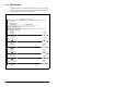
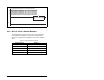
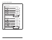
Figure 8.6 – Main Routine (Continued)
This rung writes the output image to the scanner. The output image is as follows:
DriveOutputImage[0] and DriveOutputImage[1] = Drive 0 Logic Command and Reference
DriveOutputImage[2] and DriveOutputImage[3] = Drive 1 Logic Command and Reference
DriveOutputImage[4] and DriveOutputImage[5] = Drive 2 Logic Command and Reference
DriveOutputImage[6] and DriveOutputImage[7] = Drive 3 Logic Command and Reference
DriveOutputImage[8] and DriveOutputImage[9] = Drive 4 Logic Command and Reference
(Note the length of the COP instruction is "5" because the Destination address is a DINT)
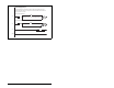
6
Copy File
Source DriveOutputImage[0]
Dest MultiDrive_Demo:O.Data[0]
Length 5
COP
This rung writes the output image to the scanner. The output image is as follows:
DriveOutputImage[0] and DriveOutputImage[1] = Drive 0 Logic Command and Reference
DriveOutputImage[2] and DriveOutputImage[3] = Drive 1 Logic Command and Reference
DriveOutputImage[4] and DriveOutputImage[5] = Drive 2 Logic Command and Reference
DriveOutputImage[6] and DriveOutputImage[7] = Drive 3 Logic Command and Reference
DriveOutputImage[8] and DriveOutputImage[9] = Drive 4 Logic Command and Reference
(Note the length of the COP instruction is "5" because the Destination address is a DINT)
(End)
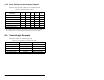
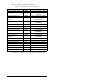
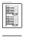
Table 8.8 – Module Parameter Settings
Control Routine Refer to...
Drive 0 Figure 8.7
Drive 1 Figure 8.8
Drive 2 Figure 8.9
Drive 3 Figure 8.10
Drive 4 Figure 8.11