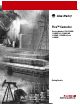
Pico™ Controller (Catalog Numbers 1760-L12AWA, -L12AWA-NC, -L12AWA-ND, -L12BWB, -L12BWB-NC, and -L18AWA) Getting Results
Important User Information Because of the variety of uses for the products described in this publication, those responsible for the application and use of this control equipment must satisfy themselves that all necessary steps have been taken to assure that each application and use meets all performance and safety requirements, including any applicable laws, regulations, codes and standards.
Table of Contents Preface Who Should Use this Manual . . . . . . . . . . . . . . . . . . . . . . . . . . . . . Purpose of this Manual . . . . . . . . . . . . . . . . . . . . . . . . . . . . . . . . . . Related Documentation . . . . . . . . . . . . . . . . . . . . . . . . . . . . . . Common Techniques Used in this Manual . . . . . . . . . . . . . . . . . . . Rockwell Automation Support . . . . . . . . . . . . . . . . . . . . . . . . . . . . Local Product Support . . . . . . . . . . . . . . . . . . . . . . .
Table of Contents ii Setting Week Day and Time. . . . . . . . . . . . . . . . . . . . . . . . . . . 2-3 Winter/Summer Time (Daylight Savings Time) . . . . . . . . . . . . 2-3 Choose Pico Operating Mode. . . . . . . . . . . . . . . . . . . . . . . . . . . . . 2-3 Selectable Start-up Behavior . . . . . . . . . . . . . . . . . . . . . . . . . . . 2-4 Pico Circuit Diagram Elements. . . . . . . . . . . . . . . . . . . . . . . . . . . . 2-4 Contacts . . . . . . . . . . . . . . . . . . . . . . . . . . . . . . .
Table of Contents iii Chapter 3 Pico Interface Socket Memory Module . . . . . . . . . . . . . . . . . . . . . . . . . . . . . . . . . . . . Loading or Storing the Circuit Diagram . . . . . . . . . . . . . . . . . . Available Memory Modules. . . . . . . . . . . . . . . . . . . . . . . . . . . . PicoSoft. . . . . . . . . . . . . . . . . . . . . . . . . . . . . . . . . . . . . . . . . . . 3-1 3-2 3-2 3-2 Appendix A Specifications Physical Specifications. . . . . . . . . . . . . . . . . . . . . . . . . .
Table of Contents iv Publication 1760-GR001A-EN-P
Preface Read this preface to familiarize yourself with the rest of the manual. It provides information concerning: • who should use this manual • the purpose of this manual • related documentation • conventions used in this manual • Rockwell Automation support Who Should Use this Manual Use this manual if you are responsible for designing, installing, programming, or troubleshooting control systems that use Pico controllers.
Preface P-2 Common Techniques Used in this Manual The following conventions are used throughout this manual: • Bulleted lists such as this one provide information, not procedural steps. • Numbered lists provide sequential steps or hierarchical information. • Italic type is used for emphasis.
Chapter 1 Pico Controller Safety Information ATTENTION Electrical Shock Hazard The electrical installation and commissioning work must only be carried out by suitably qualified personnel. Do not work on the device when the power is turned on.
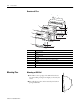
1-2 Pico Controller Overview of Pico 1 7 2 Del Alt 3 4 8 Esc 7 Del Ok 5 Alt 8 Esc 6 Ok 5 8 3 5 Item 1 2 3 4 5 6 7 8 Mounting Pico Description Incoming Power Inputs Power/Run LED Keypad Socket for memory module or PC interface cable Outputs LCD display Write-On Surface Mounting on DIN Rail 1 1. Hook Pico to the top edge of the DIN rail and rotate into place while pressing down slightly as shown by the arrow. 2. Pico will clip into place and is secured by the built-in spring mechanism.
Pico Controller 1-3 Mounting on a Mounting Plate Pico can be screwed to a mounting plate with the three or four feet which are included. Click Connecting Pico Pico Inputs 1760-L12BWB and 1760-L12BWB-NC 28.8 V l = 3.3 mA/24 V I7, I8 = 2.2 mA/24 V 1 15 V 0 5V +24 V l7, l8 0V >1A Ue = 24 V --(20.4-28.8 V ---) Ie = 80 mA 0V +10 V 10 V 5V 5-7 lb-in 3.
1-4 Pico Controller Pico Inputs 1760-L12AWA-NC, 1760-L12AWA, and 1760-L12AWA-ND 264V l1–I6 = 0.5 mA 240 V l1–I6 = 0.25 mA 120 V I7, I8 l = 6 mA 240 V l = 4 mA 120V 1 ≥ 79V 0 ≤ 40V L1 L2 >1A Ue = 120/240 V 50/60 Hz (90 to 264V) le = 40 mA 120V 20 mA 240V 5-7 lb-in. 3.
Pico Controller 1-5 Pico Inputs 1760-L18AWA 264 V l1–I6, I9 –I12 = 0.5 mA 240 V l1–I6, I9 –I12 = 0.25 mA 120 V I7, I8 l = 6 mA 240 V l = 4 mA 120 V 1 > 79 V 0 < 40 V L1 L2 >1A Ue = 120/240 V 50/60 Hz (85–264 V) le = 70 mA 120 V 35 mA 240 V 5-7 lb-in. 3.5 mm L1 l1 L2 I2 120/240 V I3 I4 I5 I6 I7 I8 I9 I10 I11 I12 Input 120/240 V Pico Outputs 1760-L18AWA 1 2 Q1 < 10 000 000 1 2 Q2 1 2 Q3 1 1 2 Q4 Q5 2 1 2 Q6 R 24 V 120 V 240 V 8A 8A 8A 2A 2A 2A 1000 W 0V ,N 10 x 58 W < 25.
1-6 Pico Controller Pico Operating Principle Pico Operating Buttons Del Button Del Alt Cursor Buttons Alt Esc Ok Function Delete object in the circuit diagram Special functions in the circuit diagram Move cursor Select menu item Choose contact numbers, values, times, etc. Next menu level, store your entry Previous menu level, cancel your entry Ok Esc Move Through Menus to Choose Values Press Del To Show system menu (press both keys at the same time). and Alt • Go to next menu level.
Pico Controller 1-7 18-Point Status Display Inputs Retention Enabled 1...5..8.... RE I P Debounce Enabled/P-Buttons Enabled Day, Time MO 02:00 ST Start-up Mode Outputs .2..5..8 Mode RUN Inputs 1, 5, 8 ON Outputs 2, 5, 8 ON Menu Display Current choice blinks in the Pico menu PROGRAM... PASSWORD.. RUN... RUN... PARAMETER PARAMETER SET CLOCK.. SET CLOCK..
1-8 Pico Controller Circuit Diagram Menu Input Contacts Circuit Connections/ Rungs Output Coil Field I1 -I2 -T1 -{Q1 I2 - 1 Branch Connections Each rung can hold four instructions, three input instructions (contacts) and one output instruction (coil or relay). Rungs are connected together through branches at the three positions between instructions. All programming of Pico can be done using the display and keypad.
Pico Controller Menu Structure 1-9 Main Menu Without Optional Password Protection STOP: Circuit diagram menu RUN: Power flow display PROGRAM... RUN PARAMETER SET CLOCK RUN Circuit Diagram STOP PROGRAM DELETE PROG CARD ... PROGRAM... RUN PARAMETER SET CLOCK PROGRAM... RUN PARAMETER SET CLOCK Parameters PROGRAM DELETE PROG CARD ... PROGRAM DELETE PROG CARD ... PROGRAM...
1-10 Pico Controller Main Menu with Password Protection Password Entry Main Menu PASSWORD... RUN PARAMETER SET CLOCK Unlock PASSWORD... RUN NOTE Publication 1760-GR001A-EN-P Password Four Wrong Entries DELETE ALL Correct Entry Status Display If you do not know the password, you can delete the old password, but the circuit diagram and data will also be deleted. To delete the password, press Ok to DELETE ALL after entering four incorrect passwords.
Pico Controller 1-11 System Menu Password Entry System PASSWORD... SYSTEM GB D F E I . Set Password Password Password Entry Change Password CHANGE PW ACTIVATE Password CHANGE PW ACTIVATE PASSWORD... SYSTEM GB D F E I . DEBOUNCE OFF P ON STOP MODE DEBOUNCE OFF DEBOUNCE ON DEBOUNCE OFF P ON STOP MODE P ON P OFF DEBOUNCE OFF P ON STOP MODE DEBOUNCE OFF P ON STOP MODE (2) RETENTION ON PASSWORD... SYSTEM GB D F E I .
1-12 Pico Controller Publication 1760-GR001A-EN-P
Chapter 2 Drawing a Circuit with Pico Operation of Pico Buttons for Drawing Circuit Diagrams Button Function Delete branch, contact, relay, or empty rung in the circuit diagram Del Alt Esc Ok Setting the Menu Language • Toggle between break and make contact • Connect contacts and relays • Add circuit connections Up/down arrows: • Change value • Move cursor up and down Left/right arrows: • Move cursor to left and right • Change between parameters • Go to previous menu level • Undo settings from pr
2-2 Drawing a Circuit with Pico Pico 1760-L18AWA also supports the following languages: • Portuguese • Dutch • Swedish • Polish • Turkish 1. Use the arrow keys to select a language. 2. Confirm with Ok. 3. Pico then shows the status display. 1 ...5 ..8 .... I1 2 34 5 6 7 8 MO or 01:00 Q1234 MO I P 02:00 .2 ..5 ..8 STOP 12-I/O Pico Setting the Time RE ST RUN 18-I/O Pico Controllers with the “-NC” designation do not have real time clocks. Setting the Real Time Clock PROGRAM ... 1 ...5 ..8 ..
Drawing a Circuit with Pico 2-3 Setting Week Day and Time SET CLOCK WINTER TIME Ok SUMMER TIME DAY : MO TIME : 14:15 left/right arrows: Move cursor up/down arrows: Change values Ok Save setting Esc Keep previous value Esc Exit Menu Winter/Summer Time (Daylight Savings Time) SET CLOCK SUMMER TIME Display: SUMMER TIME Winter time is set Display: WINTER TIME Summer time is set Ok Esc Choose Pico Operating Mode Toggle Settings Exit Menu The two Pico operating modes are RUN and STOP.
2-4 Drawing a Circuit with Pico Selectable Start-up Behavior It is possible to select the operating mode to be activated when Pico is powered up. You can choose start-up in “RUN” mode or in “STOP” mode through the System Menu.
Drawing a Circuit with Pico 2-5 Retentive Actual Values With Pico 1760-L12BWB, 1760-L12BWB-NC, and 1760-L18AWA, it is possible to save the actual values of markers, timers and counters in the event of a power failure. The quantities and values that may be retained are found in the following table. For further information see the Pico Controller User Manual, publication number 1760-UM001A-EN-P.
2-6 Drawing a Circuit with Pico Basic Output Energize { On Instruction On Output Maintained/Flip-Flop Output On Instruction On Output S,R Set Instruction Latching Output On On Reset Instruction Output Publication 1760-GR001A-EN-P On
Drawing a Circuit with Pico Example: Creating a Circuit Diagram 2-7 Interconnecting Contacts and Relays Connecting Pico 1. Connect S1 to Pico input terminal I1 2. Connect S2 to Pico input I2 3. Connect load M1 to Pico output Q1 CR1 S1 S2 I1-I2----{Q1 M1 CR1 Pico circuit diagram Draw Circuit in Circuit Diagram Menu Start Status Display I 12 3 4 5 6 7 8 1 ...5 ..8 .... MO RE or MO 14:15 Q1234 02:00 P PROGRAM... RUN ST PROGRAM... .2 ..5 ..
2-8 Drawing a Circuit with Pico Insert Contact “I2” I1 Ok I1 I1 I1 I1 Ok I1 I1 I2 I2 Ok Draw Connection Between Contact and Relay Coil I1-I2 I1-I2 Alt I1-I2--- I1-I2--- Choose Relay Coil “Q1” I1-I2--- Ok I1-I2------{Q1 I1-I2------{Q1 Ok I1-I2------{Q1 Ok Publication 1760-GR001A-EN-P
Drawing a Circuit with Pico 2-9 Change Operating Mode PROGRAM DELETE PROG I1-I1----{Q1 Esc PROGRAM... Esc RUN PROGRAM... RUN PARAMETER Ok SET CLOCK.. Pico now in RUN mode Test Circuit Diagram PROGRAM... STOP PROGRAM... STOP PARAMETER PARAMETER SET CLOCK... SET CLOCK...
2-10 Drawing a Circuit with Pico Operate Switch “S1” and “S2” “S1” on I1-I2----{Q1 I1-I2----{Q1 “S2” on I1-I2----{Q1 Relay “Q1” picks up Return to Status Display with ESC 12............ I 12 3 4 5 6 7 8 I1-I2----{Q1 Esc MO RE or 13:34 Esc Q1234 MO I 02:00 P ST 1.........RUN STOP 12-I/O Pico 18-I/O Pico In the next example, a timing relay will be added to the circuit. Status display is activated. Choose STOP mode. Ok Ok PROGRAM... RUN PARAMETER SET CLOCK..
Drawing a Circuit with Pico Function Relay Types Circuit Diagram Symbol 2-11 Function Relay Type Timing relay with on-delay, with and without random switching Timing relay with off-delay, with and without random switching Timing relay, single pulse Timing relay, flashing Counter relay, up/down counter Time switch, weekday/time (only in Pico models with clock) Analog comparator relay (only in Pico models with 24V dc) Timing Relay Timing Relay with on delay, with and without random switching on Trigg
2-12 Drawing a Circuit with Pico Timing Relay with Off-Delay, with and without Random Switching ? on Trigger on Reset on Timer Output t t With random switching, the relay contact switches randomly at any time up to the specified time value (shown shaded in figure).
Drawing a Circuit with Pico 2-13 Timing Relay, Flashing Flash Frequency = 1/2 x setpoint on Trigger on Reset on Timer Output t t t Parameter Display for Timing Relays Switch Function 00.00 Accumulated Time Setpoint Time Units S 30.
2-14 Drawing a Circuit with Pico Parameter Display for Counter Relays Setpoint Opt. direction (connected) Count Input 0230 { DIR { CNT RES Reset (not connected) Accumulated Value 0000 Counter Number C1 + Parameter Display (Access Control) Real Time Switch Example: Real Time Switch 1 switches on Monday through Friday between 6:30 and 9:00 and again between 17:00 and 22:30 (5:00 pm and 10:30 pm).
Drawing a Circuit with Pico 2-15 Analog Comparator Available functions: • I7 ≥ I8, I7 ≤ I8 • I7 ≥ Setpoint, I7 ≤ Setpoint • I8 ≥ Setpoint, I8 ≤ Setpoint The analog comparator can compare voltages from 0V to 10V (setpoints “0.0” to “10.0”). NOTE Analog signals of sensors typically fluctuate by several millivolts. For stable switching the setpoints should differ by at least 0.2V (switching hysteresis). Do not use any relay with output energize or impulse relay coil functions.
2-16 Drawing a Circuit with Pico Text Display (1760-L18AWA Only) The Text Display is used to display eight freely definable messages on the Pico screen. Each text block displays up to 48 characters from the Pico display character set (ASCII + Pico special characters). If the Text Display is enabled, the text entered via PicoSoft is displayed. If several Text Displays are enabled, the next screen is displayed every 4 seconds. When Text Display D1 is enabled it stays displayed (fault indication).
Drawing a Circuit with Pico Example: Using a Function Relay 2-17 Conventional Circuit Pico switches M1 with 10 seconds delay. CR1 S1 S2 I1-I2----{M1 M1-------TT1 T1-------{Q1 T1 10.
2-18 Drawing a Circuit with Pico Select Trigger Relay for Time I1-I2----{M1 I1-I2----{M1 M1-------{Q1 M1-------TT1 I1-I2----{M1 2X Ok M1-------TT1 Insert Timing Relay Contact I1-I2----{M1 I1-I2----{M1 M1-------TT1 Ok 2X M1-------TT1 I1 I1-I2----{M1 M1-------TT1 T1 Select Parameter Access I1-I2----{M1 M1-------TT1 T1 Publication 1760-GR001A-EN-P 2X Ok X S 00.
Drawing a Circuit with Pico 2-19 Set “10 Seconds” X S 00.00 { TRG T1 RES + 2X X S 00.00 { TRG T1 RES + 10.00 TRG T1 RES + X S { 2X back to circuit diagram Ok Connect Timing Relay Contact to New Output Relay I1-I2----{M1 M1-------TT1 T1 Alt I1-I2----{M1 M1-------TT1 T1 3X I1-I2----{M1 3X M1-------TT1 Ok T1-------{Q1 Change Pico to RUN to test the program.Test the circuit as shown for the first example.
2-20 Drawing a Circuit with Pico Basic Circuits Significance of Logic Values Value “0” “1” Function Make contact open, break contact closed, relay coil not energized Make contact closed, break contact open, relay coil energized Negation (NOR) I1 1 0 Q1 0 1 I1---------{Q1 Permanent Contact (Unconditional Rung) --1 Q1 1 -----------{Q1 Flip-Flop Output I1 0 0 to 1 0 0 to 1 State Q1 0 0 1 1 Q1 0 1 1 0 I1--------- Q1 Series Connection (AND) Publication 1760-GR001A-EN-P I1 0 1 0 I2 0 0 1 I3 0 0
Drawing a Circuit with Pico 2-21 Parallel Connection (OR) I1 0 1 0 1 0 1 0 1 I2 0 0 1 1 0 0 1 1 I3 0 0 0 0 1 1 1 1 Q1 0 1 1 1 1 1 1 1 Q2 1 1 1 1 1 1 1 0 I1--------{Q1 I2 I3 I1--------{Q2 I2 I3 Exclusive OR Circuit (XOR) I1 0 1 0 1 I2 0 0 1 1 Q1 0 1 1 0 I1-I2------{Q1 I1-I2 Motor Start/Stop Circuit I1 0 1 0 0 1 I2 0 0 0 1 1 Contact Q1 0 1 1 0 0 Coil Q1 0 1 1 0 0 I1--I2-----{Q1 Q1 Alternatively: I1--------SQ1 I2--------RQ1 Publication 1760-GR001A-EN-P
2-22 Drawing a Circuit with Pico Publication 1760-GR001A-EN-P
Chapter 3 Pico Interface Socket The Pico interface socket, which is beneath a protective cap, accepts the optional Pico memory module, or connects Pico to a PC using the optional PC interface cable and the PicoSoft software. This allows you to copy the circuit diagrams to and from the PC and/or memory module. Memory Module Memory modules are available as an optional accessory. Each memory module can store a single Pico circuit diagram.
3-2 Pico Interface Socket Loading or Storing the Circuit Diagram You can only transfer the program from Pico to the memory module or vice versa in the STOP mode. DEVICE ->CARD: Transfer circuit diagram and parameter settings from Pico to the memory module. DEVICE CARD - CARD->DEVICE: Transfer circuit diagram and parameter settings from the memory module to Pico. CARD DEVICE DELETE CARD DELETE CARD: Delete the contents of the memory module.
Appendix A Specifications Physical Specifications Specification Weight Ambient temperature, (operation) Storage Temperature Operating Humidity Emitted interference, interference immunity Standards and regulations Approvals 1760-L12xxx 1760-L18AWA 200g (7 oz) 300g (10.
A-2 Specifications Dimensions Pico 1760-L12BWB-NC, -L12BWB, -L12AWA-NC, -L12AWA, L12AWA-ND 50 1.97" 110 4.33" 90 3.54" 102 4.02" 45 1.77" 10.75 0.423" 4.5 0.177" 47.5 1.87" 56.5 2.22" 58 2.28" M4 35.75 1.41" 71.5 2.81" Pico 1760-L18AWA 16.25 0.640" 75 2.96" 16.25 0.640" 110 4.33" 90 3.54" 102 4.02" 45 1.77" M4 4.5 0.177" 47.5 1.87" 56.5 2.22" 58 2.28" 107.5 4.
Index A Allen-Bradley contacting for assistance P-2 support P-2 Analog comparator 2-15 B Basic circuit Exclusive OR circuit (XOR) 2-21 Flip-flop output 2-20 Impulse relay 2-20 Motor start/stop circuit 2-21 Negation (NOR) 2-20 Permanent contact 2-20 Series connection (AND) 2-20 Break contact 2-4 Buttons 1-6 Use in circuit diagrams 2-1 C Cable 3-2 Change operating mode 2-3 Circuit diagram Access relay parameters 2-18 Choosing relay type 2-8 Displaying 2-7 Example 2-7, 2-17 Inserting contacts 2-7 Loading 3-2
2 Index R related publications P-1 Relay types Overview 2-4 S Setting the time 2-3 Setting week day 2-3 Software 3-2 Startup behavior 2-4 Status display 1-7 Summer time 2-3 Symbols in circuit diagram 1-8 T Terminals, inputs/outputs 1-3 Publication 1760-GR001A-EN-P Text display 2-16 Time switch 2-14 Parameter display 2-14 Timing relays 2-11 Parameter display 2-13 troubleshooting contacting Allen-Bradley for assistance P-2 W Winter time 2-3 Wiring diagrams 1760-L12AWA-NC, 1760-L12AWA, and 1760-L12AWA-N
Back Cover Publication 1760-GR001A-EN-P - June 2000 2 Supersedes Publication 1764-6.1 - February 1999 and 1764-6.1-DU1 - September 1999 PN 40072-085-01(A) © 2000 Rockwell International Corporation. Printed in the U.S.A.