Pico and Pico GFX-70 Programmable Controllers Selection Guide 1760
Pico and Pico GFX-70 Programmable Controllers Publication 1760-SG001F-EN-P - May 2006
Pico and Pico GFX-70 Programmable Controllers Pico Overview 3 Small, Simple, and Flexible The Allen-Bradley Pico controller performs simple logic, timing, counting, and real-time clock operations. For enhanced functionality and performance, the Pico GFX controller adds the use of a graphic display while offering advanced programming features like PID control, a high-speed counter, and Boolean sequences.
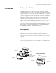
Pico and Pico GFX-70 Programmable Controllers Pico GFX-70 Components and Connections With its multi-function display, the Pico GFX-70 controller adds more flexibility and capability to the Pico family of Allen-Bradley controllers. It displays text, date, time, and even your own custom bitmaps. These graphics can be used as operator interface, or linked to control operations to provide real-time feedback.
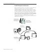
Pico and Pico GFX-70 Programmable Controllers 5 Pico Remote Processor The remote processor is used for terminal mode operation of Pico controllers and I/O modules. Use the remote mounting processor with Pico controllers, Pico expansion I/O, and Pico GFX-70 controllers. Perform text messaging and make data adjustments using the display/keypad unit. 1760-L18... 1760-L20... 1760-L12... DEL ESC 1760-LDF...
Pico and Pico GFX-70 Programmable Controllers Specifying a Pico Controller System Follow these steps as you specify your Pico Controller system. Step 1. 2. 3. 4. 5. 6. 7.
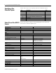
Pico and Pico GFX-70 Programmable Controllers Pico Control 7 Pico GFX-70 Control Programming Keypad ✔ Pre-programmed memory module Picosoft software ✔ ✔ ✔ Picosoft pro software Programming rungs, Max ✔ 128 ✔ 256 Pico-Link Number of Pico-link stations 8 Pico-link communication rate Pico-link length, Max 10 KBits/s to 1000 KBits/s 1000 m (3280 ft) Pico-link data transfer, Max Function Blocks 32 double words Timer Counter ✔ ✔ ✔ ✔ Analog comparator Operating hours counter ✔ ✔ ✔ ✔ 7-Day t
Pico and Pico GFX-70 Programmable Controllers Select Keypad Programming or Programming Software Pico controllers, with on-board keypad and LCD display, can be programmed from the front keypad. Models without the keypad and LCD display are programmed by using PicoSoft Pro programming software or by installing a pre-programmed memory module. Use the Keypad The keypad is an option on the display unit which is shown on page 17.
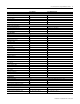
Pico and Pico GFX-70 Programmable Controllers 9 Table 1 Programming Software Selection Catalog Number 1760-PICOSOFTPRO 1760-CBL-PC02 1760-PICOPRO-PC02 Description PicoSoft Pro programming software Programming cable, PC to processor PicoSoft Pro Software and cable kit (includes 1760-PICOSOFTPRO and 1760-CBL-PC02) Software Compatibility If you are using programming software to program the Pico controller, be sure that you are using the correct software version. IMPORTANT PicoSoft version 6.
Pico and Pico GFX-70 Programmable Controllers Select Communications The Pico controller supports 2 connection methods. • Point-to-point serial interface with remote processor, 1760-RM-PICO • DeviceNet communications module The Pico GFX-70 supports 3 connection methods.
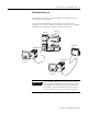
Pico and Pico GFX-70 Programmable Controllers 11 Pico-Link with GFX-70 Devices This topology allows: • processing of additional inputs and outputs. • faster and improved control using decentralized programs. • synchronize date and time. • read and write inputs and outputs. • send values to other stations. • receive values from other stations. • load a program to or from another station. • high level of real-time capability.
Pico and Pico GFX-70 Programmable Controllers Terminal Mode Using the Point-to-Point Serial Interface TERMIN AL Active Station Remote Station This interface connection allows the reading of input/output states as well as the reading and writing of marker ranges. This data can be used for setpoint entry or for display functions. The stations have different functions. The active station controls the point-to-point connection. The remote station responds to the requests of the active station.
Pico and Pico GFX-70 Programmable Controllers 13 DeviceNet Communications Module The Pico DeviceNet module, 1760-DNET, allows you to have a Pico controller operate as a slave device on the DeviceNet network. The DeviceNet module connects to the Pico controller like an expansion I/O module. It can be used with the Pico 18- and 20-point controllers and the Pico GFX-70 controller. 24V dc power must be provided to the device.
Pico and Pico GFX-70 Programmable Controllers Select Pico Controllers, I/O Pico Controllers and Accessories Select Pico controllers for up to 20 I/O points. Add a Pico expansion I/O module for up to 40 I/O points. Table 2 Pico Controllers Selection Cat. No.
Pico and Pico GFX-70 Programmable Controllers 15 Table 3 Pico Expansion I/O Module Selection Cat. No. Input Voltage Category Number of Inputs (Digital) Number of Outputs 1760-IA12XOW6I 120 / 240V ac 12 6 (isolated relay) 1760-IB12XOB8 24V dc 12 8 (transistor) 1760-IB12XOW6I 24V dc 12(1) 6 (isolated relay 1760-OW2 n/a 0 2 (relay) (1) (1) Four of the digital dc inputs can alternately be used as 0...10V dc analog inputs. These inputs can be used as either digital or analog, not both.
Pico and Pico GFX-70 Programmable Controllers Digital I7 and I8 Inputs Analog Inputs I1 I3 I2 I5 I4 I7 I6 Del Connection Cable Esc Q1 Q2 Q3 I8 Alt Ok 1760-L12BWB 1760-L12BWB-NC 1760-L12BWB-ND Q4 Output LEDs Input/Output Simulator The DC Simulator, 1760-SIM, can be used to simulate Pico inputs and outputs to test and troubleshoot programs. The simulator contains input simulator board, output simulator board, and wall-mount power supply.
Pico and Pico GFX-70 Programmable Controllers 17 Table 5 Pico GFX I/O Modules Selection Cat. No.
Pico and Pico GFX-70 Programmable Controllers Table 7 Pico GFX-70 Selection 1760-CBL-5M Point-to-point serial interface cable, 5 m (16.4 ft) 1760-CBL-INT01 Pico-link cable, 0.3 m (1 ft) 1760-CBL-INT03 Pico-link cable 0.8 m (2.6 ft) 1760-CBL-INT05 Pico-link cable 1.
Pico and Pico GFX-70 Programmable Controllers 19 Point-to-Point Serial Interface Cables The serial interface cables are available in two lengths. Table 8 Serial Cable Selection Cat. No. Description 1760-CBL-2M Point-to-point serial interface cable, 2 m (6.6 ft) 1760-CBL-5M Point-to-point serial interface cable, 5 m (16.4 ft) Cables for Pico-Link between Processors The 1760-LDFC and 1760-LDFCA processors have two Pico-Link terminals. Up to 8 of these processors can be connected together.
Pico and Pico GFX-70 Programmable Controllers The protective cover, 1760-NDC, is designed to be used in aggressive environments. This protects the display and keypad against mechanical damage or destruction. Protection to IP65 is maintained. The protective cover can be sealed to prevent unauthorized access. Mounting Feet Mounting feet are required for attaching processors and I/O modules to a panel. Three mounting feet are sufficient for a device with four mounting points.
Pico and Pico GFX-70 Programmable Controllers Specifications 21 Pico and Pico GFX-70 Specifications Table 10 Environmental Specifications Specification Pico Pico GFX-70 Operating temperature (Installed horizontally/vertically) -25…55 °C (-13…131 °F) -25…55 °C, (-13…131 °F) Display legibility -25…55 °C (-13…131 °F) -5…50 °C, (-23…122 °F) Storage/transport temperature -40…70 °C (-40…158 °F) -40…70 °C (-40…158 °F) Relative humidity (IEC 60068-2-30) 5 to 95% non-condensing 5 to 95% non-condens
Pico and Pico GFX-70 Programmable Controllers Table 12 Pico DC Controllers Power Supply Specifications Incoming Power 1760-L12DWD 1760-L12DWD-ND 1760-L18DWD-EX 1760-L18DWD-EXND 1760-L12BBB 1760-L12BBB-ND 1760-L12BWB 1760-L12BWB-NC 1760-L12BWB-ND 1760-L18BWB-EX 1760-L20BBB-EX 1760-L20BBB-EXND 1760-IB12XOW6I 1760-IB12XOB8 12V dc, +30%, -15% 12V dc, +30%, -15% 24V dc, +20%, -15% 24V dc, +20%, -15% Rated voltage Rated value Range 10.2…15.6V dc 10.2…15.6V dc 20.4…28.8V dc 20.4…28.
Pico and Pico GFX-70 Programmable Controllers 23 Table 14 Pico 120/240V ac Controllers and Expansion I/O Input Specifications Specification 1760-L12AWA 1760-L12AWA-NC 1760-L12AWA-ND 1760-L18AWA 1760-L18AWA-EX 1760-L18AWA-EXND 1760-IA12XOW6I(1) Input current R1 to R12, I1 to I6 (1760-L18AWA-xx also I9 to I12) 0.5 mA at 230V ac 50 Hz, 0.25 mA at 115V ac 60 Hz 0.5 mA at 230V ac 50 Hz 0.
Pico and Pico GFX-70 Programmable Controllers Table 15 Pico DC Controllers and Expansion I/O Input Specifications Specification 1760-L12DWD 1760-L12DWD-ND 1760-L18DWD-EX 1760-L18DWD-EXND 1760-L12BBB 1760-L12BBB-ND 1760-L12BWB 1760-L12BWB-NC 1760-L12BWB-ND 1760-L18BWB-EX 1760-L18BWB-EXND 1760-L20BBB-EX 1760-L20BBB-EXND 1760-IB12XOB8(1) 1760-IB12XOW6I Number of analog inputs 2 (4 inputs 1760-L18DWD-xx) 2 4 Input Type dc voltage dc voltage dc voltage Signal Range 0…10V dc 0…10V dc 0…10V dc
Pico and Pico GFX-70 Programmable Controllers 25 Table 16 Pico Controllers and Expansion I/O Relay Output Specifications Specification 1760-L12AWA-xx 1760-L12BWB-xx 1760-L12DWD-xx 1760-L12NWN-xx Isolation to EN 50178 Between Two Contacts 1760-L18AWA-xx 1760-L18BWB-xx 1760-L18DWD-xx 1760-L18NWN-xx 1760-IA12XOW6I 1760-IB12XOW6I 300V ac reinforced insulation Making Capacity AC-15 COS φ = 0.
Pico and Pico GFX-70 Programmable Controllers Table 17 Pico Controllers and Expansion I/O Transistor Output Specifications Specification 1760-L12BBB 1760-L12BBB-ND 1760-IB12XOB8 1760-L20BBB-EX 1760-L20BBB-EXND Short Circuit Tripping Current, I for Load ≤10 milli-ohm 0.
Pico and Pico GFX-70 Programmable Controllers 27 Table 19 GFX I/O Modules Input Specifications Specification 1760-IB12XOW4IF, 1760-IB12XOW4IOF 1760-IB12XOB4IF, 1760-IB12XOB4IOF 1760-IA12XOW4I Number of digital inputs 12 12 Inputs usable as analog inputs (I7, I8, I11, I12) 4 0 Inputs usable as high-speed inputs (I1, I2, I3, I4) 4 0 Rated voltage 24V dc 120/240V ac Off-state voltage I1 to I6 and I9 to I10: < 5V dc I7, I8, I11, I12: < 8V dc 0…40V ac On-state voltage I1 to I6 and I9 to I10:
Pico and Pico GFX-70 Programmable Controllers Table 20 GFX I/O Modules Relay Output Specifications Specification 1760-IA12XOW4I, 1760-IB12XOW4IF 1760-IB12XOW4IOF, 1760-OW2 Number of relay outputs 4 (2 for the 1760-OW2) Type of outputs Relays In groups of 1 Connection of outputs in parallel to increase the output Not permissible Protection for an output relay Miniature circuit-breaker B16: 16 A or fuse (slow-blow): 8 A Potential isolation to mains power supply, input, PC interface, memory mo
Pico and Pico GFX-70 Programmable Controllers 29 Table 21 GFX I/O Modules Transistor Output Specifications Specification 1760-IB12XOB4IF, 1760-IB12XOB4IOF Transistor Outputs 4 Rated voltage 24V dc (20.4V dc…28.8V dc) Supply current On 0 state: 18 mA (typical), 32 mA (Max) On 1 state: 24 mA (typical), 44 mA (Max) Rated current at state 1, maximum 0.5 A Residual current at state “0” per channel < 0.
Pico and Pico GFX-70 Programmable Controllers Mounting Dimensions Figure 1 Pico 12-Point Controller 10.75 mm (0.423 in.) 50 mm (1.97 in.) 90 mm (3.54 in.) 45 mm (1.77 in.) 110 mm (4.33 in.) 102 mm (4.02 in.) 4.5 mm (0.177 in.) 47.5 mm (1.87 in.) 56.5 mm (2.22 in.) 58 mm (2.28 in.) M4 35.75 mm (1.41 in.) 71.5 mm (2.81 in.) Figure 2 Pico 18- and 20-Point Controllers and Pico Expansion I/O Modules 16.25 mm (0.640 in.) 16.25 mm (0.640 in.) 75 mm (2.96 in.) M4 45 mm (1.77 in.) 110 mm 90 mm (4.
Pico and Pico GFX-70 Programmable Controllers 31 2.28" Figure 3 Pico Remote Processor 1760-DU… and 176-RM… 58 176-RM… 22.5 0.89" 30 1.18" 75 22.5 0.89" 36.2 1.43" 20.5 0.81" 2.95" 43.2 1.7" 27.5 1.08" Figure 4 Pico GFX-70 Display Unit (with and without keypad) 22.3 30 86.5 32 17 Specification 1760-DU and 1760-DUB Front dimensions (W x H x D), Approx. 1760-DUB (with keys): 86.5 x 86.5 x 21.5 mm (3.41 x 3.41 x 0.85 in.) 30 28.25 20 28.25 62 13.
Pico and Pico GFX-70 Programmable Controllers Figure 7 Pico GFX-70 Processor Unit 90 Specification 1760-LDF, 1760-LDFA, 1760-LDFC, 1760-LDFCA Dimensions (W x H x D), 107.5 x 90 x 30 mm Approx. (4.23 x 3.54 x 1.18 in.) 38.75 30 16.25 75 38.75 4.5 29.5 16.25 107.5 Figure 8 Pico GFX-70 I/O Modules 90 Specification 88.1 19 25 Dimensions when fitted (W x H x D), Approx. Dimensions when removed (W x H x D), Approx.
Pico and Pico GFX-70 Programmable Controllers 33 Fill in the Selection Worksheet Catalog Number Description Programming Software and Cable PicoSoft Pro Programming Software 1760-PICOSOFTPRO(1) 1760-CBL-PM02 1760-CBL-PC02 1760-PICOPRO-PC02 Communications Module 1760-DNET Pico Controllers 1760-L12AWA 1760-L12AWA-NC 1760-L12AWA-ND 1760-L12BBB 1760-L12BBB-ND 1760-L12BWB 1760-L12BWB-NC 1760-L12BWB-ND 1760-L12DWD 1760-L12DWD-ND 1760-L12NWN 1760-L12NWN-ND 1760-L18AWA-EX 1760-L18AWA-EXND 1760-L18BWB-EX 1760-L18
Pico and Pico GFX-70 Programmable Controllers Catalog Number Description 1760-RM-GFX Pico GFX-70 Remote Processor Unit Pico GFX-70 I/O Modules 1760-IA12XOW4I (12) 120V ac inputs, (4) relay outputs 1760-IB12XOW4IF (12) 24V dc inputs, (4) relay outputs, analog input 1760-IB12XOW4IOF (12) 24V dc inputs, (4) relay outputs, analog input and output 1760-IB12XOB4IF (12) 24V dc inputs, (4) transistor outputs, analog input 1760-IB12XOB4IOF (12) 24V dc inputs, (4) transistor outputs, analog input and output Di
Pico and Pico GFX-70 Programmable Controllers 35 Publication 1760-SG001F-EN-P - May 2006
Rockwell Automation Support Rockwell Automation provides technical information on the Web to assist you in using its products. At http://support.rockwellautomation.com, you can find technical manuals, a knowledge base of FAQs, technical and application notes, sample code and links to software service packs, and a MySupport feature that you can customize to make the best use of these tools.