Distributed Power System SA3100 Drive Configuration and Programming Instruction Manual S-3056-1
Throughout this manual, the following notes are used to alert you to safety considerations: ! ATTENTION: Identifies information about practices or circumstances that can lead to personal injury or death, property damage, or economic loss. Important: Identifies information that is critical for successful application and understanding of the product.
CONTENTS Chapter 1 Introduction Chapter 2 Configuring the UDC Module, Regulator Type, and Parameters 2.1 Adding a Universal Drive Controller (UDC) Module ........................................ 2-1 2.2 Entering the Drive Parameters ........................................................................ 2-3 2.3 Configuring the Vector with Constant Power Regulator .................................. 2-5 2.3.1 Power Module Data Screen (Vector with Constant Power)................... 2-5 2.3.
Chapter 5 On-Line Operation 5.1 Loading the UDC Module’s Operating System ................................................5-1 5.2 Loading the Drive Parameters and UDC Tasks ...............................................5-1 5.3 Running, Stopping, and Deleting UDC Application Tasks ...............................5-2 5.4 UDC Information Log and Error Log ................................................................5-3 Appendix A SA3100 Vector Regulator Register Reference .................................
List of Figures Figure 2.1 – Adding a UDC Module.......................................................................... 2-2 Figure 2.2 – Adding Flex I/O..................................................................................... 2-3 Figure 2.3 – Drive Parameter Entry Screen (Vector with Constant Power).............. 2-4 Figure 2.4 – Power Module Data Parameter Entry Screen (Vector with Constant Power)...................................................................................
IV SA3100 Drive Configuration and Programming
List of Tables Table 1.1 – SA3100 Documentation (Binder S-3053) .............................................. 1-2 Table 1.2 – SA3100 Power Structure Service Manual Cross Reference ................. 1-2 Table 2.1 – Restricted Drive Type Combinations ..................................................... 2-2 Table 2.2 – Maximum Slip Per Number of Poles...................................................... 2-8 Table 2.3 – Standard Resolvers ......................................................................
VI SA3100 Drive Configuration and Programming
CHAPTER 1 Introduction SA3100 drives operate under the control of the AutoMax™ Distributed Power System (DPS). DPS drives are controlled through coordination among: • Tasks written by the programmer for the AutoMax Processor. • Tasks written by the programmer for the Universal Drive Controller (UDC) module. • The control algorithm and a number of software routines executed by the Power Module Interface (PMI) regulator.
Related Publications The user must become familiar with the other instruction manuals that describe the SA3100 drive system. The documentation that describes the SA3100 drive is contained in binder S-3053 and is listed in table 1.1. Table 1.
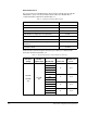
Table 1.2 – SA3100 Power Structure Service Manual Cross Reference AC Input Voltage DC Bus Input Voltage Nominal HP Frame Size Use Service Manual 1336 Force- B 6.11 C 6.12 D 6.13 E 6.14 F 6.14 G 6.15 H 6.
Table 1.2 – SA3100 Power Structure Service Manual Cross Reference AC Input Voltage DC Bus Input Voltage Nominal HP Frame Size Use Service Manual 1336 Force- B 6.11 C 6.12 D 6.13 E 6.14 F 6.16 G 6.15 H 6.
CHAPTER 2 Configuring the UDC Module, Regulator Type, and Parameters ! ATTENTION: Only qualified personnel familiar with the construction and operation of this equipment and the hazards involved should install, adjust, operate, or service this equipment. Read and understand this manual and other applicable manuals in their entirety before proceeding. Failure to observe this precaution could result in severe bodily injury or loss of life.
Step 4. Select a product type and a regulator (control) type for both drive A and drive B. See section 2.1.1 for regulator selection rules. The remainder of this chapter assumes that you have selected an SA3100 Drive Product with a Vector with Constant Power Regulator or Volts/Hertz Regulator. Step 5. Select OK to add the UDC module to the rack and return to the Rack Configuration screen. Figure 2.
2.2 Entering the Drive Parameters Drive parameters are application-specific data that describe your installation’s Power Modules, feedback devices, and motors. This information is loaded to the UDC module, which in turn automatically downloads it to the PMI when the two are first connected over the fiber-optic link. This information is also stored off-line with the Programming Executive. Note that the drive parameters will be retained by the UDC module during a Stop All fault or command to the rack.
Step 3. Use the Configure Parameters option to access the Parameter Entry screens. For the Vector with Constant Power regulator, you must access the Power Module Data, Motor Data, Feedback Data, and Meter Port Selection screens (see figure 2.3). For the Volts per Hertz regulator you must access the Power Module Data, Configuration Data - Setup, Volts/Hz Characteristic, Feedback Data, and Meter Port Selection screens. An additional screen is used for configuring Flex I/O.
2.3 Configuring the Vector with Constant Power Regulator The following sections (2.3.1 to 2.3.4) describe the parameter entry screens for the SA3100 Vector with Constant Power regulator. These screens are accessed by selecting SA3100 as the product type and Vector with Constant Power as the regulator type when configuring the UDC module parameters. If your drive uses the Volts per Hertz regulator refer to section 2.4. 2.3.
Power Module • Part Number Select a part number from the list of supported Power modules (x nnn, where x is the voltage code and nnn is the horsepower rating). The current ratings in the list are the rated RMS currents at the drive’s default carrier frequency as listed in Appendix H, with no overload at 40° ambient temperature. The power module is capable of 150% of the maximum amps value for 1 minute. There is no default selection. You must choose a part number from the list.
• Constant Magnetization, Manual Compensation, or Constant Power These selections define the method the system will use to determine the value used for magnetizing current in the control algorithm. The default selection is Manual Compensation which allows operation in the constant power region up to 2:1. In this case, the value in register 104/1104 (FLX_REF%) is used to scale local tunable STATOR_IZ_E1% where 4095 equals full magnetizing current.
If a warning appears, it is likely that the maximum RMS current that can be supplied to the motor at the torque overload ratio level selected is too high for the Power Module selected. See Appendix E for more information on determining the maximum RMS current that will result from the ratio entered. • Frequency at Rated Voltage (Hz) (Range: 1 to 600) This value is used to determine the frequency at which the motor enters the constant power range. Enter the value in Hz. Resolution is 0.1 Hz.
2.3.2.2 Constant Power Motor Data Screen When Constant Power is selected, a new screen is displayed, and the following information must be entered. See figure 2.6. Figure 2.6 – Motor Data Parameter Entry Screen used for Constant Power • Rated Power (Range: 1 HP to 800 HP or 1 KW to 600 KW) Enter the power rating of the motor and select HP (default) or KW. There is no default value. NOTE: 1 HP = 0.746 KW. • Rated Motor Voltage (Volts RMS) (Range: 100V to 575V) Enter the rated RMS motor voltage.
• Speed (RPM) (Range: 10 to 10,000) Enter all speed values in RPM; the resolution is 1 RPM. There are no default values. Base: Enter the base (rated) speed of the motor. The base speed value represents the speed where the motor enters the constant power region. This value is used to determine the rated slip of the motor at the rated motor frequency. This value is found on the motor’s nameplate. S1: Enter the speed at which maximum voltage is reached.
If a warning appears, it is likely that the maximum RMS current that can be supplied to the motor at the torque overload ratio level selected is too high for the Power Module selected. See Appendix E for more information on determining the maximum RMS current that will result from the ratio entered. Base: Enter the base (rated) torque overload ratio. O1-O4: Enter the additional overload ratios at each speed, S1 to S4. This information is located on the motor design data sheet.
2.3.3 Feedback Data Screen (Vector with Constant Power) The Feedback Data Parameter Entry Screen allows you to enter specific information about the resolver connected to the Resolver and Drive I/O module on the PMI. See figure 2.7. Figure 2.7 – Feedback Data Parameter Entry Screen (Vector with Constant Power) • Over Speed Limit (RPM) (Range: 10 to 10,000) This value is used to determine the maximum safe output frequency of the drive. There is no default value.
Table 2.3 – Standard Resolvers Resolver Base Part No. x1 x2 x5 613469 -1R -1S 613469 -2R -2S 800123 -R -S -T 800123 -1R -1S -1T 800123 -2R -2S -2T Suffix For the most accurate velocity control, always select the resolver (x1, x2, or x5) with the maximum speed closest to, and greater than, the maximum speed of your application. See the SA3100 PMI instruction manual for more information regarding the Resolver & Drive I/O module and the supported resolvers.
2.3.4 PMI Meter Port Selection Screen (Vector with Constant Power) The Meter Port Selection Parameter Entry screen allows you to enter specific information about what variables are to be output on the four PMI D/A channels (the four meter ports on the PMI motherboard. See figure 2.8. Figure 2.8 – PMI Meter Port Selection Entry Screen (Vector with Constant Power) Table 2.4 lists the values that can be displayed on the PMI meter ports using the Vector with Constant Power regulator.
Table 2.
2.4 Configuring the Volts per Hertz (V/Hz) Regulator The following sections (2.4.1 to 2.4.5) describe the parameter entry screens for the SA3100 Volts per Hertz regulator. These screens are accessed by selecting SA3100 as the product type and Volts per Hertz as the regulator type when configuring the UDC module. If your drive uses the Vector with Constant Power regulator refer to section 2.3.
• MCR Connected To Output Contactor If you have a motor control relay (MCR) on the output of the drive (output contactor), select this option. If there is only a manual disconnect switch and no contactor under automatic control, do not select the output contactor option. The default selection is no contactor. Power Module • Part Number Select a part number from the list of supported Power modules (x nnn, where x is the voltage code and nnn is the horsepower rating).
2.4.2 Configuration Data - Setup (Volts per Hertz) The Configuration Data - Setup parameter screen allows you to enter the following information about the Volts per Hertz regulator. See figure 2.10. Figure 2.10 – Configuration Data Setup Parameter Entry Screen (Volts per Hertz) • Asynchronous or Synchronous Carrier The default is asynchronous carrier, which can be used for most applications.
• Current Limit Selecting this button enables the current limit function in the drive. Specify the limiting current value in the Current Limit Amps field. Resolution is 0.1 amp. • Current Limit Delay Current Limit Delay provides a time delay for the drive to operate in the current limit region before executing the current limiting functions. If the regulator detects that output current has reached the specified limit, it will respond by setting bit 2 or 3 in register 204/1204.
2.4.3 V/Hz Characteristic Screen (Volts per Hertz) The V/Hz Characteristic parameter screen allows you to enter specific information about the motor and V/Hz regulator. See figure 2.11. Figure 2.11 – V/Hz Characteristic Parameter Entry Screen (Volts per Hertz) • Maximum Frequency (Hertz) Maximum Frequency defines the maximum frequency which will be output from the drive. Resolution is 0.001 Hz.
• Voltage Boost Volts (Volts) Voltage Boost Volts and Voltage Boost Frequency define a point on the V/Hz curve where the slope changes, typically to accommodate low frequency instability. Resolution is 0.01V. Voltage Boost Volts is typically used to extend the range at constant torque to lower frequencies. This can also be used to avoid the “low frequency instability region” which is found in some motors with low or no connected inertia and low friction loads.
• Over Speed Limit (RPM) (Range: 10 to 20,000) This value is used to determine the maximum safe output frequency of the drive. There is no default value. Over Speed Limit should generally be equal to or less than the motor maximum safe speed or the driven equipment maximum safe speed, whichever is lower. If a value less than Rated Full Load Speed of the motor is entered, a warning will be generated. • Speed Feedback Type No Speed Feedback is the default setting.
The Minimum Value must not be less than -32768. The Maximum Value must not be greater than 32767. The Minimum Value must be less than the Maximum Value. Note that the PMI meter ports have 8-bit resolution and are updated on the average of every 1.0 milliseconds. See the PMI Regulator instruction manual (S-3057) for more information about the PMI meter ports. See section 3.7.2.1 of this instruction manual for information about resolution of data. Table 2.
2.5 Configuring Flex I/O The Configure Flex I/O Parameter Entry Screen allows you to configure your Flex I/O Modules, if Flex I/O is being used with your system. See figure 2.14. Figure 2.14 – Flex I/O Parameter Entry Screen A maximum of three Flex I/O modules is allowed. Module 0 and Module 1 must be digital; Module 2 can be either digital or analog. • Module 0 Select a digital I/O module from the pull-down list. Only the supported digital I/O modules will be displayed. There is no default selection.
• Channel 0 to Channel 7 If an analog I/O module is selected for Module 2, you must configure the channels for the analog module appropriately. No error checking is done by the system. The channels all default to “not used”. 2.6 Generating Drive Parameter Files and Printing Drive Parameters When you have completed all of the drive parameter screens, you can select “Close” to leave the Parameter Entry Screens and return to the master rack diagram with the UDC module selected.
2-26 SA3100 Drive Configuration and Programming
CHAPTER 3 Configuring the UDC Module’s Registers ! ATTENTION:Only qualified electrical personnel familiar with the construction and operation of this equipment and the hazards involved should install, adjust, operate, or service this equipment. Read and understand this manual and other applicable manuals in their entirety before proceeding. Failure to observe this precaution could result in severe bodily injury or loss of life.
• The Command Registers view is used to configure pre-defined drive control registers that are written to either by an AutoMax application task or by a UDC application task and then sent to the PMI. • The Feedback Registers view is used to configure the feedback registers that display the current status of the drive. These registers are written to by the PMI.
3.1 Register and Bit Reference Conventions Used in this Manual Register numbers are shown using the convention A/B, where A is the drive A register number and B is the drive B register number. Note that the Interrupt Status Control registers and the Application registers are the same for both drive A and drive B. Register descriptions are shown in the following format: Register Name Register Numbers [Functional description] Sug. Var.
Table 3.1 – UDC Module Configuration Views and Registers View 3-4 Register Range Described in Section: Port 0 Flex I/O Drive A: 0- 11 Drive B: 12-23 3.2 UDC/PMI Communication Status Registers Drive A: 80-89 Drive B: 1080-1089 3.3 Command Registers Drive A: 100-108 Drive B: 1100-1108 3.4 Feedback Registers Drive A: 200-222 Drive B: 1200-1222 3.5 Application Registers Updated Every Scan 300-599 3.6 Application Registers Updated Every Nth Scan 1300-1599 3.
Table 3.2 – UDC Module Dual Port Memory Register Organization.
3.2 Flex I/O Port Registers (Registers 0-23) The Flex I/O Port 0 view is used to assign variable names and configure the registers used for the Flex I/O port on the PMI. If you have no hardware attached to this port, do not configure these registers. All of the Flex I/O data for PMI A and PMI B is combined into one section of the dual port memory. The appropriate variable configuration screen will be displayed based on the hardware that you have specified is connected to the port.
Table 3.4 lists the Flex I/O modules that are supported by the SA3100 system. Refer to the appropriate Flex I/O instruction manuals for specific information about the Flex I/O modules used in your system. Table 3.4 – Supported Flex I/O Modules Catalogue Number Publication Number 16 Point DC Sink Input 1794-IB16 1794-5.4 16 Point DC Source Output 1794-OB16 1794-2.3 16 Point DC Source Input 1794-IV16 1794-5.28 16 Point DC Sink Output 1794-OV16 1794-5.29 1794-IB10XOB6 1794-5.
3.2.2 Analog Data Formats Data is returned from the Flex I/O module’s analog-to-digital converter with 12-bit resolution. The value is left-justified into a 16-bit field, reserving the most significant bit for a sign bit.
3.2.3 Flex I/O Status and Error Codes Register 10/22 contains status and error codes for Flex I/O Module 0 and Module 1. The memory map is shown in table 3.6. Table 3.6 – Register 10/22 - Flex I/O Module 0 and Module 1 Faults Bit Name Description 0 Flex Bus Fault Set if the Flex Bus Interface on the PMI Regulator has faulted. 1 Flex Clock Warning Set if the Flex I/O clock is not running. 2 Flex Scratch Pad Warning Set if a read/write Flex I/O memory error is detected.
Register 11/23 contains status and error codes for Flex I/O Module 2. The memory map is shown in table 3.7. Table 3.7 – Register 11/23 - Flex I/O Module 2 Faults Bit Name Description 0 Module 2 Not Plugged In Set if no device is detected at Module 2 port. 1 Module 2 Communication Error Set if there is a serial communication error with Module 2. 2 Module 2 Bad ID Set if a non-supported module ID is received from Module 2 or if the module ID received does not match the configured ID.
3.3 UDC/PMI Communication Status Registers (Registers 80-89/1080-1089) The UDC/PMI Communication Status Registers display the status of the fiber-optic communications between the UDC module and the PMI. Two consecutive errors will be indicated by a communication fault, and the drive will stop. Refer to register 202/1202, bit 15, for more information. Note that the communication status registers are for system use only and can only be monitored.
UDC Module Communication Status Register (Continued) 80/1080 DMA Format Error The DMA Format Error bit is set if the length of the received message does not match the length encoded in the message itself. Bit 4 Hex Value: Sug. Var. Name: Access: UDC Error Code: LED: 0010H N/A Read only N/A N/A Transmitter Underrun The Transmitter Underrun bit is set if the USC reports a transmit first-in, first-out underrun. Bit 5 Hex Value: Sug. Var.
UDC Module Communication Status Register (Continued) 80/1080 Multiplexed Data Verification Failure The Multiplexed Data Verification Failure bit is set if data which is multiplexed into command/feedback messages does not verify correctly. Bit 9 Hex Value: Sug. Var.
UDC Module CRC Error Count Register This register contains the number of messages with CRC errors received by the UDC module from the PMI. 82/1082 Sug. Var. Name: Units: Range: Access: UDC Module Format Error Count Register This register contains the number of messages with format errors received by the UDC module from the PMI. N/A Counts N/A Read only 83/1083 Sug. Var.
PMI Communication Status Register (Continued) 84/1084 Overrun Error The Overrun Error bit is set if the USC reports a receive first-in, first-out overrun. Bit 3 Hex Value: Sug. Var. Name: Access: UDC Error Code: LED: 0008H N/A Read only N/A N/A DMA Format Error The DMA Format Error bit is set if the length of the received message does not match the length encoded in the message itself. Bit 4 Hex Value: Sug. Var.
PMI Communication Status Register (Continued) 84/1084 Multiplexed Data Verification Failure The Multiplexed Data Verification Failure bit is set if data multiplexed into command/feedback messages does not verify. Bit 9 Hex Value: Sug. Var. Name: Access: UDC Error Code: LED: 0200H N/A Read only N/A N/A Invalid PMI Start Operating System Address The Invalid PMI Start Operating System Address bit is set by the PMI if the operating system is not within the allocated operating system address area.
PMI Communication Status Register (Continued) 84/1084 PMI Operating System Overflow into Stack Memory The PMI Operating System Overflow into Stack Memory bit is set by the PMI if the loading of the PMI operating system will overrun the PMI stack memory area. Hex Value: Sug. Var. Name: Access: UDC Error Code: LED: Bit 15 8000H N/A Read only N/A N/A This condition will cause the loading of the PMI operating system to fail.
UDC Module Fiber-Optic Link Status Register This register shows the current operating state of the fiber-optic link to the PMI. The lower byte (bits 0-7) shows the actual link status while the upper byte (bits 8-15) shows whether the communication taking place is synchronized or not. 88/1088 Sug. Var. Name: Units: Range: Access: N/A N/A N/A Read only If the lower byte is equal to: xx01H: the UDC module is waiting for a request from the PMI for an operating system.
3.4 Command Registers (Registers 100-199/1100-1199) The Command Registers view is used to configure command registers. These registers are used for command data sent to the PMI by the UDC module at the end of every scan of the UDC Processor. Note that the bits in these registers (except bit 15 in register 100/1100) are used to command action only and do not indicate the status of the action commanded. The feedback registers (registers 200/1200 to 299/1299) are provided for this purpose.
Drive Control Register (Continued) 100/1100 Bridge Test Enable The Bridge Test Enable bit is set to begin the bridge test procedure. Bit 2 Hex Value: Sug. Var. Name: Access: UDC Error Code: LED: 0004H BRG_TST@ Read/Write N/A N/A The bridge test turns on individual or sets of power devices in the Power Module in order to verify the gate cable connections and power device operation. The value in the Bridge Test Code register (105/1105) is used to select which power devices to turn on.
Drive Control Register (Continued) 100/1100 Synchronous Transfer Request* Bit 7 *Reserved for future use. Hex Value: Sug. Var. Name: Access: UDC Error Code: LED: The application task sets the Synchronous Transfer Request bit to begin matching the Voltage, Period, and Phase of the drive’s PWM output to an external source. 0080H SX_REQ@ Read/Write N/A N/A When synchronization is ready, register 200, bit 7 (SYN_OK@) is turned on to indicate that the synchronous transfer may be done.
Drive Control Register (Continued) 100/1100 Bit 11 Reserved for future use. Hex Value: Sug. Var. Name: Access: UDC Error Code: LED: 0800H Read only N/A N/A Bit 12 Reserved for Future Use. Hex Value: Sug. Var. Name: Access: UDC Error Code: LED: UDC Task Running The UDC Task Running bit is a status bit that indicates that the UDC task is running. This bit is used by the PMI Regulator to prevent the minor loop from running if the UDC task is not running.
I/O Control Register (Continued) 101/1101 External Fault LED The External Fault LED command bit is set by the application task to turn on the EXT FLT LED on the PMI Regulator. Bit 2 Hex Value: Sug. Var. Name: Access: UDC Error Code: LED: Auxiliary Output The Auxiliary Output command bit is set to turn on the auxiliary output on the Resolver & Drive I/O board. Bit 4 Hex Value: Sug. Var.
I/O Control Register (Continued) 101/1101 Enable External Strobe Falling Edge The Enable External Strobe Falling Edge bit is set to enable the external strobe on the resolver to capture the position of the resolver when the falling edge of the external strobe is detected. As long as this bit is set, the external strobe is enabled. Bit 9 Hex Value: Sug. Var.
Torque Reference Register (Vector) In Vector mode, register 102/1102 functions as the Torque Reference Register. The value in this register is the reference sent to the PMI Regulator for use in the Vector control algorithm minor loop. 102/1102 Sug. Var. Name: Units: Range: Access: TRQ_REF% Counts -4095 to +4095 Read/Write This value corresponds to the torque produced by the configured maximum motor current (rated motor current ∗ motor overload ratio).
Bridge Test Code Register The value written to the Bridge Test Code register determines which power device to turn on during the bridge test. 105/1105 Sug. Var.
3.5 Feedback Registers (Registers 200-299/1200-1299) The Feedback Registers view is used to configure the feedback registers that display the current status of the drive. These registers are updated by the PMI and sent to the UDC module over the fiber-optic link before every scan of the UDC task. The status of these registers is retained after a Stop All. Drive Status Register 200/1200 The bits in the Drive Status register indicate the current state of the drive.
Drive Status Register (Continued) 200/1200 Torque / Frequency Reference Saturation Minus In Vector mode, the PMI sets the Torque Reference Saturation Minus bit when the system is requesting maximum negative torque from the drive. In Volts per Hertz mode, the Frequency Reference Saturation Minus bit is set when the current limit option has been selected, and current feedback is at the negative limit. Hex Value: Sug. Var.
Drive Status Register (Continued) 200/1200 Fault Detected The PMI Regulator sets the Fault Detected status bit if any fault is detected. This bit is reset by bit 8 of register 100/1100. Bit 8 Hex Value: Sug. Var. Name: Access: UDC Error Code: LED: 0100H FLT@ Read only N/A N/A See the description of the Drive Fault register (202/1202) for more information. Warning Detected The Warning Detected status bit is set if any warning is detected. This bit is reset by bit 9 of register 100/1100.
I/O Status Register 201/1201 The bits in the I/O Status register indicate the current state of the inputs on the Resolver & Drive I/O board. Run Permissive Input The Run Permissive Input bit displays the status of the input signal connected to pin A on the DRIVE I/O connector. When the signal is present, this bit is set. Bit 0 Hex Value: Sug. Var. Name: Access: UDC Error Code: LED: 0001H RPI@ Read only N/A RPI This signal typically originates from the drive’s coast-to-stop circuit.
I/O Status Register (Continued) 201/1201 Auxiliary Input 5 The Auxiliary Input 5 bit reflects the status of the 115 VAC auxiliary input 5 on the Resolver & Drive I/O board. When the input signal is present, this bit is set. Bit 5 Hex Value: Sug. Var. Name: Access: UDC Error Code: LED: Resolver Gain Calibrated The Resolver Gain Calibrated status bit is set when the resolver gain calibration procedure is complete. This procedure is performed when the value stored in local tunable RES_GAN% is set to zero.
I/O Status Register (Continued) 201/1201 STATOR_IZ_E1% Tuning Complete (Vector with Constant Power) The STATOR_IZ_E1% Tuning Complete status bit is set to indicate that the system has successfully tuned the value in STATOR_IZ_E1%. Hex Value: Sug. Var. Name: Access: UDC Error Code: LED: Bit 10 0400H TUNED_IZ@ Read only N/A N/A Note that this procedure is used in Vector with Constant Power applications only. Refer to Appendix B for more information on this procedure.
Drive Fault Register (Continued) 202/1202 Ground Current Fault The Ground Current Fault bit is set if ground current exceeds the hardware trip point. Bit 2 Hex Value: Sug. Var. Name: Access: UDC Error Code: LED: 0004H FLT_GND@ Read only 1021 EXT FLT For models A001/Q001 and A003/Q003 the hardware trip point is 20A @ 10V. For all other models it is 100A @ 10V.
Drive Fault Register (Continued) 202/1202 Charge Bus Time-Out Fault The Charge Bus Time-out Fault bit is set to indicate any of the conditions listed below. Register 222/1222 provides additional diagnostics if this fault occurs. Bit 6 Hex Value: Sug. Var. Name: Access: UDC Error Code: LED: 0040H FLT_CHG@ Read only 1024 EXT FLT and P.M. FLT • The DC bus is not fully charged within 10 seconds after the bus enable bit (register 100/1100, bit 4) is set.
Drive Fault Register (Continued) 202/1202 Overspeed Fault The Overspeed Fault bit is set if the motor’s velocity exceeds the value entered as the Overspeed Trip (RPM) configuration parameter. Bit 10 Hex Value: Sug. Var. Name: Access: UDC Error Code: LED: 0400H FLT_OSP@ Read only 1010 EXT FLT Power Technology Fault The Power Technology Fault bit is set to indicate a problem with the AC power technology circuit on the PMI Regulator motherboard. Bit 11 Hex Value: Sug. Var.
Drive Fault Register (Continued) 202/1202 Communication Lost Fault The Communication Lost Fault bit is set if the fiber-optic communication between the PMI Processor and the UDC module is lost due to two consecutive errors of any type. Bit 15 Hex Value: Sug. Var. Name: Access: UDC Error Code: LED: 8000H FLT_COM@ Read only 1015 COMM OK This bit is set only after communication between the PMI Regulator and UDC module has been established. This bit should be used in the run permissive logic for the drive.
Drive Warning Register 203/1203 Ground Current Warning The Ground Current Warning bit is set if ground current exceeds the ground current level stored in local tunable GIT_E1%. Bit 2 Hex Value: Sug. Var. Name: Access: UDC Error Code: LED: Voltage Ripple Warning The Voltage Ripple Warning bit is set if the ripple on the DC bus exceeds the voltage ripple threshold value stored in local tunable VRT_E0%. 0004H WRN_GND@ Read only N/A N/A Bit 3 Hex Value: Sug. Var.
Drive Warning Register (Continued) 203/1203 Bit 6 Reserved for future use. Hex Value: Sug. Var. Name: Access: UDC Error Code: LED: 0040H Read only N/A N/A Over Temperature Warning The Over Temperature Warning bit is set if the Power Module’s heatsink reaches a temperature of 90° C. Bit 7 Hex Value: Sug. Var.
Drive Warning Register (Continued) 203/1203 Bit 12 Reserved for future use. Hex Value: Sug. Var. Name: Access: UDC Error Code: LED: 1000H Read only N/A N/A Flex I/O Communication Warning The Flex I/O Communication Warning bit is set if a Flex I/O communication problem is detected and logged in registers 10, 11, 22, or 23. Refer to tables 3.6 and 3.7. Bit 13 Hex Value: Sug. Var.
Power Device Status Register (Continued) 204/1204 Phase V-Upper IOC A The Phase V-Upper IOC A bit is set if an overcurrent is detected in the phase V upper power device. Bit 1 Hex Value: Sug. Var. Name: Access: UDC Error Code: LED: 0002H V_UPA@ Read only N/A N/A Phase W-Upper IOC A The Phase W-Upper IOC A bit is set if an overcurrent is detected in the phase W upper power device. Bit 2 Hex Value: Sug. Var.
Power Device Status Register (Continued) 204/1204 Inverter Power Device Fault The Inverter Power Device Fault bit is set if the gate driver turns off an output power device (IGBT) to protect it from an overcurrent. Bit 6 Hex Value: Sug. Var. Name: Access: UDC Error Code: LED: 0040H IPMA@ Read only N/A N/A Bit 3 in register 202 will also be set. If an output short circuit occurs, a high current will flow in the IGBT causing its collector-to-emitter voltage to increase to a level much higher than normal.
Power Device Status Register (Continued) 204/1204 Bit 14 Reserved for future use. Hex Value: Sug. Var. Name: Access: UDC Error Code: LED: 4000H Read only N/A N/A Bit 15 Reserved for future use. Hex Value: Sug. Var. Name: Access: UDC Error Code: LED: Interlock Register 8000H Read only N/A N/A 205/1205 Interlock tests are executed whenever bit 0, 1, 2, or 4 of register 100/1100 is set. The first problem detected will be indicated by the corresponding bit in the Interlock register.
Interlock Register (Continued) 205/1205 RPI Missing The RPI Missing bit is set if the Run Permissive input on the Resolver & Drive I/O board is not on. Bit 2 Hex Value: Sug. Var. Name: Access: UDC Error Code: LED: 0004H IC_RPI@ Read only N/A N/A Faults Need Reset The Faults Need Reset bit is set if previous faults (register 202/1202) have not been cleared. Bit 3 Hex Value: Sug. Var.
Interlock Register (Continued) 205/1205 MCR Did Not Close The MCR Did Not Close bit is set if the optional output contactor did not close when commanded to do so. Bit 7 Hex Value: Sug. Var. Name: Access: UDC Error Code: LED: 0080H IC_MCR@ Read only N/A N/A Bit 8 Reserved for future use. Hex Value: Sug. Var. Name: Access: UDC Error Code: LED: 0100H Read only N/A N/A Bit 9 Reserved for future use. . Hex Value: Sug. Var.
Ground Current Feedback (Amps) Register The Ground Current Feedback (Amps) register contains the measured RMS ground current. This value is scaled in amps times 10. For example, 50.1 amps would be represented as 501. 208/1208 Sug. Var. Name: Units: Range: Access: Voltage Feedback (Volts RMS) Register In Vector mode, the Voltage Feedback (Volts RMS) register contains the measured RMS motor voltage scaled in volts. In Volts per Hertz mode, this register contains the fundamental frequency RMS volts.
Iq Feedback Normalized Register (Vector) In Vector mode, register 213/1213 functions as Iq Feedback Normalized register. This register contains the Iq (torque producing) component of the current feedback. The data is normalized so that +/- 4095 counts corresponds to the torque reference (TRQ_REF%). 213/1213 Sug. Var. Name: Units: Range: Access: Output Frequency Register (V/Hz) In Volts per Hertz mode, registers 212/1212 and 213/1213 function as the Output Frequency register.
Revolutions Per Minute Register The Revolutions Per Minute register contains the speed of the motor in RPM. A positive number in this register indicates a forward direction; a negative number indicates a reverse direction. 217/1217 Sug. Var. Name: Units: Range: Access: RPM% RPM N/A Read only Note that this register is not intended for closed loop control. Slip Feedback Register (Vector) In Vector mode, register 218/1218 functions as the Slip Feedback register.
Diagnostic Fault Code Register 222/1222 The Diagnostic Fault Code register displays an error code to help diagnose the cause of a problem reported in other registers. Sug. Var. Name: Units: Range: Access: Note that this register is available for monitoring only. It cannot be referenced in an application task. DIAG_FLT% N/A N/A Read only AC Power Technology Calibration and Power-Up Faults: If any of the following calibration and power-up diagnostic faults occurs, replace the PMI Regulator motherboard.
Diagnostic Fault Code Register (Continued) 222/1222 Run Time AC Power Technology Hardware Faults (Continued): Code Fault Description/Action 22 A/D interrupt overrun An interrupt from the power technology circuit was detected before the previous interrupt was processed. Replace the PMI Regulator motherboard. 23 Gate power test 1 fault Gate power is on when the MCR is off and Gate Enable is on. Replace the PMI Regulator motherboard. 24 Not used.
3.6 Application Registers (Registers 300-599, Every Scan) (Registers 1300-1599, Every Nth Scan) The application registers are used to pass application-specific data between the AutoMax Processor and the UDC module. Memory is allocated for a maximum of 600 application registers. There are 300 registers that can be used every scan (registers 300-599) and 300 registers that can be used every Nth scan (registers 1300-1599). “N” is defined in register 2001.
to respond to an interrupt from the UDC module. Registers within this range that are written to by an AutoMax task are read by the UDC operating system from dual port memory and copied into the UDC local memory at the beginning of the Nth scan. See figure 3.2. The following data types can be defined in the application register area: boolean (bit), integer (16 bits), double integer (32 bits), and real (32 bits).
Figure 3.2 – Nth Scan Interrupts 3-52 SA3100 Drive Configuration and Programming Scan 2 Scan 3 Scan 4 Input A Write “every scan" registers that are outputs from task A Latch “every scan" registers that are inputs to task B Write “Nth scan" registers that are outputs from both tasks A and B Write “every scan” registers that are outputs from task B. Run B Output B Write “every scan” registers that are outputs from task A UDC operating system generates interrupt to AutoMax Processor.
3.7 UDC Module Test I/O Registers (Registers 1000-1017) This view is used to configure the UDC module’s Test Switch Inputs Register and the Meter Port Setup Registers. 3.7.1 UDC Module Test Switch Inputs Register (Register 1000) This view is used to configure the register that displays the status of the test switches and LED indicators on the UDC module. Writing to this register will not change the state of the LEDs. The status of this register is retained during a Stop All.
UDC Test Switch Inputs Register (Continued) 1000 COMM A OK LED The COMM A OK LED bit shows the status of the COMM A OK LED on the UDC module ( 0 = OFF; 1 = ON). Bit 9 Hex Value: Sug. Var. Name: Access: UDC Error Code: LED: Drive A Fault LED The Drive A Fault LED bit shows the status of the Drive A Fault LED on the UDC module ( 0 = OFF; 1 = ON). Bit 10 Hex Value: Sug. Var.
3.7.2 UDC Module Meter Port Setup Registers (Registers 1000-1017) Registers 1001-1017 are used to configure the UDC module’s meter ports. This configuration determines what variables from the UDC module’s dual port memory are to be displayed on the meter ports at the end of the UDC scan. At system power-up, the output values of the ports are reset to zero. To map a UDC variable to a specific meter port at power-up, refer to table 3.8 and use the following procedure.
3.7.2.1 Resolution of Meter Port Data For meter ports, the output values will be clamped at the outside (+/-10V) limits. Note that if you select to display a data range that is narrower than the actual range of the data, your output values will not change until the value returns to within the range you selected to display. In other words, data is being updated at the rate described above, but the actual output voltage may not change.
Meter Port 1 UDC Module Meter Port 1 Register Number Register UDC register number (0 - 2044) to be mapped to meter port 1. 1002 Sug. Var. Name: Units: Range: Access: N/A N/A N/A Read/Write UDC Module Meter Port 1 Bit Number Register Bit number of the UDC register specified in register 1002 that is to be mapped to port 1. Enter a value of 100 (bit 00) to 115 (bit 15) as required. Enter a value of zero if all of the register’s bits are to be displayed. 1003 Sug. Var.
Meter Port 2 UDC Module Meter Port 2 Register Number Register UDC register number (0 - 2044) to be mapped to meter port 2. 1006 Sug. Var. Name: Units: Range: Access: N/A N/A N/A Read/Write UDC Module Meter Port 2 Bit Number Register Bit number of the UDC register specified in register 1002 that is to be mapped to port 2. Enter a value of 100 (bit 00) to 115 (bit 15) as required. Enter a value of zero if all of the register’s bits are to be displayed. 1007 Sug. Var.
Meter Port 3 UDC Module Meter Port 3 Register Number Register UDC register number (0 - 2044) to be mapped to meter port 3. 1010 Sug. Var. Name: Units: Range: Access: N/A N/A N/A Read/Write UDC Module Meter Port 3 Bit Number Register Bit number of the UDC register specified in register 1002 that is to be mapped to port 3. Enter a value of 100 (bit 00) to 115 (bit 15) as required. Enter a value of zero if all of the register’s bits are to be displayed. 1011 Sug. Var.
Meter Port 4 UDC Module Meter Port 4 Register Number Register UDC register number (0 - 2044) to be mapped to meter port 4. 1014 Sug. Var. Name: Units: Range: Access: N/A N/A N/A Read/Write UDC Module Meter Port 4 Bit Number Register Bit number of the UDC register specified in register 1002 that is to be mapped to port 4. Enter a value of 100 (bit 00) to 115 (bit 15) as required. Enter a value of zero if all of the register’s bits are to be displayed. 1015 Sug. Var.
3.8 Interrupt Status and Control Registers (Registers 2000-2047) This view is used to configure registers that control the operation of interrupts to a task on an AutoMax Processor in the rack and to enable CCLK in the rack. These registers are used for Drive A and B. Only one UDC task should write to these registers. Note that the status of these registers is not retained after a Stop All. Interrupt Status Control Register The Interrupt Status Control register contains the following information.
Interrupt Status Control Registers (Continued) 2000 CCLK Counting Bit 5 Hex Value: Sug. Var. Name: Access: UDC Error Code: LED: 0010H N/A Read only N/A N/A Enable CCLK on the Multibus Backplane CCLK must be enabled in the rack for the UDC module to execute its task(s) and communicate synchronously with the PMI. Bit 6 Hex Value: Sug. Var. Name: Access: UDC Error Code: LED: 0001H N/A Read/Write N/A N/A Only one module per rack should enable CCLK.
Scans Per Interrupt Register The Scans Per Interrupt register contains the number of times a UDC task is to be scanned between updates of the Nth scan application registers. 2001 Sug. Var. Name: Units: Range: Access: SPI% N/A See below. Read/Write Note that you must write the desired value to this register before you turn on CCLK. The default value is zero (i.e., not applicable because an interrupt is not being used but is updated each scan). One is a permissible value.
3-64 SA3100 Drive Configuration and Programming
CHAPTER 4 Application Programming for DPS Drive Control ! ATTENTION:Only qualified personnel familiar with the construction and operation of this equipment and the hazards involved should install, adjust, operate, or service this equipment. Read and understand this manual and other applicable manuals in their entirety before proceeding. Failure to observe this precaution could result in severe bodily injury or loss of life.
UDC tasks must be written in the Control Block language, a language designed specifically for drive control. To differentiate them from Control Block tasks written for AutoMax Processors, they must be specified as UDC tasks in the Programming Executive software. Like Control Block tasks on AutoMax Processors, UDC tasks can include a number of BASIC language statements and functions; however, those that allow task suspension or delay are not supported.
All common input values for the UDC task are first read from the dual port memory and then stored in a local buffer in order to have a consistent context for evaluation. The task is then executed. After the task has been executed, the common output values from the UDC task are written from the local memory buffer to dual port memory. The only exception to this pattern are the common variables in the “Nth” scan application register area.
Step 4. SCAN_LOOP block/Enabling CCLK This control block tells the UDC operating system how often to execute the task based on the constant clock (CCLK) signal on the rack backplane. Note that the CCLK signal must be enabled by a task in the rack before any UDC tasks in the rack can be scanned beyond their SCAN_LOOP blocks. Note that CCLK must be enabled again after a STOP ALL in the rack.
Step 6. Motor thermal overload protection Electronic thermal overload protection for SA3100 drives is normally provided by the THERMAL OVERLOAD block. The following briefly describes how the THERMAL OVERLOAD block works, how to program the block, and what adjustments are possible. Each UDC task must contain a THERMAL OVERLOAD block, unless motor thermal overload protection is provided by a hardware device. See J-3676, the Control Block Language instruction manual, for the structure of the block.
Consider an example in which LIM_BAR is defined to be 150% of full load current, THRESHOLD is 114%, and TRIP_TIME is 60 seconds. When I_FDBK is at 100%, CALC_RISE will reach a steady state value of 1000 (1002 / 10). With THRESHOLD at 114%, the trip point for CALC_RISE will be 1300 (1142 / 10). If I_FDBK is at steady state (100%) and then is stepped to 150%, CALC_RISE will integrate up to 1300 in 60 seconds and OVERLOAD will turn on. The OVERLOAD output will stay on until the rise decays to less than 1000.
Like all tunable values in the AutoMax environment, the values of these UDC task tunables are retained through a power loss. Note that the programmer can also define other local tunable variables for application-specific purposes, but that the total number of all local tunables in a UDC task cannot exceed 127. 4.2.2.1 Calculating Local Tunable Values Depending upon the type of local tunable variable, the “CURRENT” value, i.e.
The exchange of command and feedback register data is synchronized through the use of the constant clock signal (CCLK) on the UDC module as described below. CCLK also enables the coordination of all UDCs in a rack because they will all use the same time base for task execution. Note that all UDC modules in a rack are not required to have the same value in the TICKS parameter of the SCAN_LOOP block in both their tasks.
CCLK_OK@ COM_FLT@ RUN_PERM@ Start Permissive Logic RUN_PERM@ Figure 4.2 – Recommended Run Permissive Logic Refer to the individual bit descriptions in this manual for more information. 4.3 AutoMax Processor Task and UDC Task Coordination Recall that all tasks running on AutoMax Processors have access to the UDC dual port registers, but that UDC tasks can only access those common variables that represent registers in their own dual port memory.
Figure 4.3 – Data/Time Flow for UDC Module and PMI 4-10 SA3100 Drive Configuration and Programming Vector * Diagnostics, Communication, Management, etc. 10 msec. (20 ticks) dual port memory application registers in UDC values to control command and AutoMax task writes new *Communication of command and feedback registers between the UDC and PMI synchronized UDC tasks and PMI control algorithms are not synchronized. The vector control algorithm runs, on the average, every 1 msec. 1.
CHAPTER 5 On-Line Operation ! ATTENTION:Only qualified personnel familiar with the construction and operation of this equipment and the hazards involved should install, adjust, operate, or service this equipment. Read and understand this manual and other applicable manuals in their entirety before proceeding. Failure to observe this precaution could result in severe bodily injury or loss of life.
The option “A” for ALL will automatically load the rack (i.e., AutoMax Processor configuration, the drive parameters for all the UDC modules in the rack, and all tasks for the rack, including all UDC tasks). The drive parameters may be loaded to the UDC module in a specified slot or to all UDC modules in the rack. When the drive parameters are loaded, the AutoMax Programming Executive will determine if the drive parameters are compatible with the existing rack configuration.
Deleting UDC Tasks When a UDC application task is deleted, any local variables which were forced are removed from the force table. The task’s error log is also cleared. 5.4 UDC Information Log and Error Log The information log and error log for a UDC task can be displayed by selecting “I” for Info/Log from the ON LINE menu. Refer to the AutoMax Programming Executive instruction manual for the procedure.
5-4 SA3100 Drive Configuration and Programming
APPENDIX A SA3100 Vector Regulator Register Reference Registers 0-23 24-79 80-89 90-99 100-106 107-199 200-222 223-299 300-599 600-999 1000 1001-1017 1018-1079 1080-1089 1090-1099 1100-1106 1107-1199 1200-1222 1223-1299 1300-1599 1600-1999 2000-2010 2011-2047 REGISTER MAP Function Flex I/O port registers System Use Only UDC/PMI comm.
FEEDBACK REGISTERS (CONTINUED) A/B 202/1202 Drive Fault Bit 0 DC bus overvoltage fault 1 DC bus overcurrent fault 2 Ground current fault 3 Instantaneous overcurrent 4 Power supply fault 6 Charge bus time-out fault 7 Over temperature fault 8 Resolver broken wire fault 9 Resolver fault 10 Over speed fault 11 Power technology fault 13 PMI bus fault 14 UDC run fault 15 Communication lost fault 203/1203 Drive Warning Bit 0 DC bus overvoltage warning 1 DC bus undervoltage warning 2 Ground current warning 3 Voltag
APPENDIX B SA3100 Volts / Hertz Regulator Register Reference Registers 0-23 24-79 80-89 90-99 100-106 107-199 200-222 223-299 300-599 600-999 1000 1001-1017 1018-1079 1080-1089 1090-1099 1100-1106 1107-1199 1200-1222 1223-1299 1300-1599 1600-1999 2000-2010 2011-2047 REGISTER MAP Function Flex I/O port registers System Use Only UDC/PMI comm.
FEEDBACK REGISTERS (CONTINUED) A/B 202/1202 Drive Fault Bit 0 DC bus overvoltage fault 1 DC bus overcurrent fault 2 Ground current fault 3 Instantaneous overcurrent 4 Power supply fault 6 Charge bus time-out fault 7 Over temperature fault 8 Resolver broken wire fault 9 Resolver fault 10 Over speed fault 11 Power technology fault 13 PMI bus fault 14 UDC run fault 15 Communication lost fault 203/1203 Drive Warning Bit 0 DC bus overvoltage warning 1 DC bus undervoltage warning 2 Ground current warning 3 Voltag
SA3100 Volts / Hertz Regulator Register Reference B-3
B-4 SA3100 Drive Configuration and Programming
APPENDIX C SA3100 Local Tunable Variables C.1 Current Minor Loop Gain Variables The stator resistance and the stator time constant values can be generated automatically by using the enable tuning command (register 100/1100, bit 1). The values generated by the system should not require adjustment. If any of these values are modified outside of acceptable limits, the new value will be ignored and the last acceptable value entered will be used.
STATOR_T_E4% The value of the Stator Time Constant is used to adjust the gain of the current minor loop. The value is entered in seconds times 10000, e.g., 50 msec (0.05 Sec) is entered as 500. Stator Time Constant Units: Default Value: Low Limit: High Limit: Step: Secs ∗ 10000 10 0 10000 1 C.2 Vector Algorithm Gain Variables The vector algorithm gain variables are used to adjust the gain of the vector control algorithm.
STATOR_IZ_E1% No Load Stator Current Tuning STATOR_IZ_E1% for Constant Power Applications The SA3100 Constant Power operating system has the capability of accommodating temperature changes via modification of the slip value. This modification of the slip value is accomplished through the use of a PMI reference magnetizing current table, which enables the PMI to determine when a load change has occurred. When a load change occurs, the output of the flux loop will increase.
STATOR_IZ_E1% (continued) No Load Stator Current Use the following procedure to implement each reference point in the speed loop calculation: Step 1. With the drive’s motor unconnected, set bits 0 and 1 of register 101/1101. Step 2. Command the speed loop to the appropriate speed reference Step 3. When the speed is reached, set bit 10 of register 101/1101 in the UDC. Step 4. Monitor register 203/1203 and bit 10 of register 201/1201. Step 5.
C.3 Volts per Hertz Voltage Point Gain Variables The seven gains below represent the seven voltage points of the V/Hz characteristic curve. When the PMI Regulator detects a set of 0 value volts per hertz characteristic gains it will calculate a curve. When the enable tuning command (register 100/1100, bit 1, PMI_TUN@) is asserted, these gains are reset to their default values. When the reset is complete register 200, bit 1 (PMI_ATC@) is set. See Appendix E (Figures E.2 and E.
P5VT_E3! This value is set to select the voltage at point 5 in the V/Hz characteristic curve. This value is entered in times 1000, e.g., 50 volts is entered as 50000. Point 5 Voltage Units: Default Value: Low Limit: High Limit: Step: P6VT_E3! This value is set to select the voltage at point 6 in the V/Hz characteristic curve. This value is entered in times 1000, e.g., 50 volts is entered as 50000.
P1HZ_E3! This value is set to select the frequency at point 1 in the V/Hz characteristic curve. This value is entered in hertz times 1000, e.g., 60 hertz is entered as 60000. P2HZ_E3! This value is set to select the frequency at point 2 in the V/Hz characteristic curve. This value is entered in hertz times 1000, e.g., 60 hertz is entered as 60000. P3HZ_E3! This value is set to select the frequency at point 3 in the V/Hz characteristic curve. This value is entered in hertz times 1000, e.g.
C.5 DC Bus Variables The programmer selects the values in the following variables to determine the drive’s response to changes in the DC bus. Note that the following relationship must be true or a drive warning will occur (register 203/1203, bit 8): PLT_E0% < UVT_E0% < OVT_E0% For more information about internal DC bus control, refer to the SA3100 Power Modules instruction manual (S-3058).
VRT_E0% Voltage Ripple Warning Threshold A drive warning is generated (203/1203, bit 3) if ripple (voltage variation) on the DC bus exceeds the value stored in this variable. The value is entered in volts. Units: Default Value: Low Limit: High Limit: Step: Volts 20 10 24 1 This diagnostic is operational after the bus has reached steady state. It is intended to be used to detect an input phase loss in the rectifier section of a three-phase AC input. However, it can also be used with a common bus supply.
RES_GAN% Resolver Gain When RES_GA% is equal to zero, the gain tuning procedure is performed automatically by the operating system. Zero is the default value. The value can range from 0 to 255 counts, with 1 count representing 0.15 volts of gain. Units: Default Value: Low Limit: High Limit: Step: Counts 0 0 255 1 This value should be generated using the auto-tuning procedure because the PMI Processor can take into account the entire resolver circuit when setting the proper gain value.
APPENDIX D Vector with Constant Power Regulator SA3100 drives may use either a vector regulator (constant torque or constant power) to control current (torque) to AC motors, or a Volts per Hertz regulation algorithm (see Appendix E). Execution of the vector algorithm is referred to as the minor loop (V/Hz does not use a current minor loop). Power conversion (DC bus to AC variable frequency, variable torque) is performed via pulse width modulation (PWM), which produces a nearly sinusoidal current waveform.
Figure D.
D.1 Dual Wound Motor D.1.1 Overview The dual wound motor is a specially designed motor which has two sets of terminals for connection to two inverters. The outputs of the inverters are connected to the parallel windings of the motor. This type of motor enables an application engineer to use a larger horsepower motor than the horsepower of the largest inverter.
D-4 Drive Configuration and Programming
APPENDIX E Volts per Hertz (V/Hz) Regulator The SA3100 volts per hertz regulator (figure E.1) uses an application dependent V/Hz characteristic curve to control the output voltage for a commanded frequency. The drive’s output voltage varies with output frequency according to the V/Hz characteristic curve, when operating in the constant torque region (V/Hz = constant). Constant power and variable torque characteristics are supported. The volts per hertz regulator supports a frequency range of 0 to 600 Hz.
When required the V/Hz curve is defined by the specification of 7 points of voltage and frequency, as shown in the figure E.2 for constant torque, and figure E.3 for variable torque. The user interface provides a default set of these points based on the parameter entry selected. The user can modify these points to satisfy specific application requirements (see chapter 2).
Figure E.
Output Volts Constant Torque Range Constant Power Range V5 V6 P5 Nameplate (V/Hz) V4 6 P6 7 P4 1 2 3 4 5 P0 V3 V0 V2 V1 F0 P3 P2 P1 F2 F1 Frequency F4 F3 F5 F6 Constant Voltage Frequency (15, 30, 50, 60, 120, 240, 400, 600 etc.) Max Frequency Figure E.
APPENDIX F Status of Data in the AutoMax Rack After a STOP_ALL Command or STOP_ALL Fault AutoMax Processor UDC Module PMI Processor LOCAL tunable variables retained retained retained LOCAL variables retained reset to 0 N/A COMMON memory variables non-volatile are retained; others are reset to 0 N/A N/A I/O variables (including UDC dual port memory inputs retained and updated; outputs are reset to 0 inputs retained and updated; outputs are reset to 0 all I/O is reset to 0 Input values, inc
F-2 SA3100 Drive Configuration and Programming
APPENDIX G Torque Overload Ratio Parameter Precautions The maximum RMS current that will be generated by the Power Module based on the entered Torque Overload Ratio must be within the limits of the selected Power Module or a warning will be generated: ∗ * Power Module Rated Amps for the selected Power Module. In some cases, however, the internal limit checking rules may be too conservative and generate a warning even when the Power Module Rated Current and Torque Overload Ratio values are consistent.
Maximum RMS Current = Square Root of [(%Torque_Overload_Ratio/100)2 x (Rated_Motor_Current2 - Iz2) + Iz2] Iz is the magnetizing current component of the Power Module output stored in local tunable variable STATOR_IZ_E1%. The value for this variable can be generated by enabling tuning in register 100/1100, bit 1. Note that you must load a complete parameter object file and UDC task to the UDC module before you can enable tuning.
APPENDIX H Default Carrier Frequency and Carrier Frequency Limit for Drive Horsepower Ranges HP Range Default Carrier Frequency Carrier Frequency Limit 1-3 4kHz 1-12kHz 7.5-30 4kHz 1-12kHz 40-60 4kHz 1-12kHz 75-125 2kHz 1-6kHz 150-250 2kHz 1-6kHz 300-500 2kHz 1-4kHz 600-650 1.5kHz 1-4kHz 800 1.
H-2 SA3100 Drive Configuration and Programming
APPENDIX I Vector with Constant Power Parameter Entry Example Overload Torque 628 ft lb 506 ft lb Rated Torque 314 ft lb Volts 460 V 266 ft lb 425 ft lb 390V 265 ft lb Amps 373 ft lb 248 ft lb 314A 280A 220 ft lb 270A 260A Rated Motor Voltage 390 Maximum Motor Voltage 460 Total Current Rating Points Base S1 S2 S3 S4 230A 5 Speed Current Overload 318 375 700 1100 1200 314 280 270 260 230 200 190 160 150 150 RPM 318 375 Base S1 Vector with Constant Power Parameter Entry Example 700 S
APPENDIX J Commissioning Procedure for Non-Constant Power Algorithim Operation Background The SA3000 and SA3100 AC vector control drives utilize the same control algorithm. This control algorithm contains a constant power algorithm to provide for load changes such as temperature. It is possible to configure both the SA3000 and SA3100 to NOT utilize this constant power algorithm.
Note: You must observe the “Alter Speed” bit and modify the motor speed two times: once to accelerate the motor to synchronous speed and once to cause the motor to return to the first-point speed. Observe the “Alter Speed” bit and modify the motor speed two times: Once to accelerate the motor to synchronous speed and once to force the motor to return to the first-point speed. After the motor has returned to the first point speed, observe the “tuned iz” bit (bit 10 of register 201/1201).
• After using the reference point data for Drive A (register 101), use the reference point data for Drive B register (1101). • Ensure that the vector orientation alignment request bit (bit 6, 0040h) is set in register 1100. • The IGNn! values for the A and B drives should be the same. The acquisition of data should be done with both drives to verify that the magnitudes of the values are similar. After the acquisition is done, the IGNn! values from Drive A should be used for Drive B.
For a 2 to 1 range; reference points one, two, three, four, five, six and seven are used. For a 3 to 1 range; reference points eight and nine are also used. For a 4 to 1 range; reference point ten is also used. Note that PMI operating system version requires internal gain tunables IGN1! to IGN9! for retention of the table data. (IGN ==> Internal Gain) Use the following procedure to implement each reference point in the speed loop calculation: Step 1.
Reference Material The following information describes step by step processor functions for the new commissioning procedure. 1. Calculate the necessary motor parameters and variables initially based on the following equations: (This represents the action taken when the PMI tune function is invoked (bit 1 of register 100/1100)). 1. Iz_rtd_start (amps) = 3 . Ist _ rtd 1. 746 * HP rtd (magnetizing current) V mot _ rtd 1. Id_rtd_start (amps) = 2 . Iz _ rtd_start 1. 1.Iq_rtd_start (amps) = 2 .
4. Calculate the remainder of the necessary motor parameters using the following measurements: 2 .V NL_rtd Ls0 = 2 .π. (stator inductance) f0 . Id_rtd_1 Vq_rtd = OLR . Iq _ rtd _ 1 .Rst _1 + 2 . V NL _ rtd 3 ( 10 ) (q - component voltage) ( 11 ) q - component voltage has to satisfy the following inequality: 2 V mot _ rtd 3 V q _ rtd > 2 ( 12 ) If the above inequality (12) is true then Vq_rtd can be used for further calculations.
It is necessary to recalculate all algorithm coefficients and variables based on motor nameplate data and the above three parameters. The equation set which allows this to be accomplished is shown below: Id_rtd = 2 .Iz_rtd Iq_rtd = 2 . I 2st_rtd I 2d_rtd Rst_0 = Rst_rtd Rr 0 = Rr_rtd = 551 . HP rtd Ψ r_rtd_start (wb) = Lm 0 = . (RPM RPM rtd 227 . synch - RPM rtd) I 2q _ rtd HPrtd . V mot_rtd . Ist_rtd p . RPMrtd . Ι q _ rtd Ψ r_rtd Id_rtd L*σs 0 = Tst .
This Page Intentionally Blank J-8 Drive Configuration and Programming
I-2 SA3100 Drive Configuration and Programming
INDEX A Access, 3-3 Application programming, 4-1 to 4-10 AutoMax and UDC task coordination, 4-9 AutoMax tasks, 4-1 calculating local tunable values, 4-7 data/time flow for UDC and PMI, 4-10 Flex I/O port registers, 3-6 local tunable variables, 4-6 to 4-7 recommended run permissive logic, 4-9 typical structure of a UDC task, 4-3 to 4-6 UDC task scan, 4-2 UDC tasks, 4-1 to 4-10 UDC/PMI task communication, 4-7 to 4-10 Application registers, 3-50 to 3-51 AutoMax rack status of data, F-1 B Flex I/O, 2-3, 2-24
resolver scan position, 3-46 resolver strobe position, 3-46 revolutions per minute, 3-47 selected variabler, 3-47 slip feedback (vector), 3-47 user analog input, 3-46 volt command (V/Hz), 3-45 voltage feedback (volts rms), 3-45 Flex I/O adding to the drive, 2-3 analog data formats, 3-8 configuring, 2-24 to 2-25 digital data formats, 3-7 Flex I/O port registers, 3-6 to 3-10 module 0 and module 1 faults, 3-9 reserved Flex I/O registers, 3-6 status and error codes, 3-9 to 3-10 G Generating drive parameter fil
feedback data (vector), 2-12 Flex I/O, 2-24 meter port selection (V/Hz), 2-22 meter port selection (vector), 2-14 motor data (vector), 2-6, 2-9 power module data (V/Hz), 2-16 power module data (vector), 2-5 V/Hz characteristic, 2-20 Service manual cross reference, 1-2 to 1-4 Sug. Var.
Index-4 SA3100 Drive Configuration and Programming
Rockwell Automation / 24703 Euclid Avenue / Cleveland, Ohio 44117 / (216) 266-7000 Printed in U.S.A.