
Instruction Manual


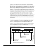
Table Of Contents
- S-3056-1 Distributed Power System SA3100 Drive Configuration and Programming Instruction Manual
- Important User Information
- Contents
- List of Figures
- List of Tables
- Chapter 1 Introduction
- Chapter 2 Configuring the UDC Module, Regulator Type, and Parameters
- 2.1 Adding a Universal Drive Controller (UDC) Module
- 2.2 Entering the Drive Parameters
- 2.3 Configuring the Vector with Constant Power Regulator
- 2.4 Configuring the Volts per Hertz (V/Hz) Regulator
- 2.5 Configuring Flex I/O
- 2.6 Generating Drive Parameter Files and Printing Drive Parameters
- Chapter 3 Configuring the UDC Module’s Registers
- 3.1 Register and Bit Reference Conventions Used in this Manual
- 3.2 Flex I/O Port Registers (Registers 0-23)
- 3.3 UDC/PMI Communication Status Registers (Registers 80-89/1080-1089)
- 3.4 Command Registers (Registers 100-199/1100-1199)
- 3.5 Feedback Registers (Registers 200-299/1200-1299)
- 3.6 Application Registers (Registers 300-599, Every Scan) (Registers 1300-1599, Every Nth Scan)
- 3.7 UDC Module Test I/O Registers (Registers 1000-1017)
- 3.8 Interrupt Status and Control Registers (Registers 2000-2047)
- Chapter 4 Application Programming for DPS Drive Control
- Chapter 5 On-Line Operation
- Appendix A SA3100 Vector Regulator Register Reference
- Appendix B SA3100 Volts / Hertz Regulator Register Reference
- Appendix C SA3100 Local Tunable Variables
- Appendix D Vector with Constant Power Regulator
- Appendix E Volts per Hertz (V/Hz) Regulator
- Appendix F Status of Data in the AutoMax Rack After a STOP_ALL Command or STOP_ALL Fault
- Appendix G Torque Overload Ratio Parameter Precautions
- Appendix H Default Carrier Frequency and Carrier Frequency Limit for Drive Horsepower Ranges
- Appendix I Vector with Constant Power Parameter Entry Example
- Index
Application Programming for DPS Drive Control
4-1
CHAPTER 4
Application Programming
for DPS Drive Control
Distributed Power Drive products are sold only as part of engineered systems. The
application programming required for each engineered system is developed in
response to each customer’s specifications. Information in this chapter is general
enough to apply to most engineered systems; however, implementation details may
vary. Always refer to your wiring diagrams for specific information about your
engineered system.
4.1 AutoMax Tasks
AutoMax tasks are used to implement safety interlocks, coordinate multiple UDCs,
and collect data from UDC modules in the rack. They can access all common memory
and I/O in the AutoMax rack, including the dual port memory in the UDC module.
AutoMax drive control tasks are generally written in control blocks and PC/Ladder
Logic language. Typically these tasks control the Drive Control register (100/1100)
and the I/O Control register (101/1101). AutoMax tasks can access registers in the
UDC’s dual port memory in the same way as tasks on the UDC module itself, i.e., by
declaring them COMMON.
4.2 UDC Tasks
UDC tasks operate on registers in the UDC dual port memory described in chapter 3,
as well as on local task-specific variables in order to control some application variable
(e.g., speed) and to calculate the required reference values for the selected control
algorithm. The UDC task is sometimes referred to as an “outer” or “major” control
loop. Note, however, that there may be more than one outer loop per task. In this
case the control loops are nested, or “cascaded,” within the UDC task.
!
ATTENTION:Only qualified personnel familiar with the construction and
operation of this equipment and the hazards involved should install,
adjust, operate, or service this equipment. Read and understand this
manual and other applicable manuals in their entirety before proceeding.
Failure to observe this precaution could result in severe bodily injury or
loss of life.
ATTENTION:Only qualified Rockwell personnel or other trained
personnel who understand the potential hazards involved may make
modifications to the application tasks. Any modifications may result in
uncontrolled machine operation. Failure to observe this precaution could
result in damage to equipment and bodily injury.