
Instruction Manual

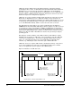
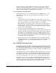
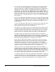
Table Of Contents
- S-3056-1 Distributed Power System SA3100 Drive Configuration and Programming Instruction Manual
- Important User Information
- Contents
- List of Figures
- List of Tables
- Chapter 1 Introduction
- Chapter 2 Configuring the UDC Module, Regulator Type, and Parameters
- 2.1 Adding a Universal Drive Controller (UDC) Module
- 2.2 Entering the Drive Parameters
- 2.3 Configuring the Vector with Constant Power Regulator
- 2.4 Configuring the Volts per Hertz (V/Hz) Regulator
- 2.5 Configuring Flex I/O
- 2.6 Generating Drive Parameter Files and Printing Drive Parameters
- Chapter 3 Configuring the UDC Module’s Registers
- 3.1 Register and Bit Reference Conventions Used in this Manual
- 3.2 Flex I/O Port Registers (Registers 0-23)
- 3.3 UDC/PMI Communication Status Registers (Registers 80-89/1080-1089)
- 3.4 Command Registers (Registers 100-199/1100-1199)
- 3.5 Feedback Registers (Registers 200-299/1200-1299)
- 3.6 Application Registers (Registers 300-599, Every Scan) (Registers 1300-1599, Every Nth Scan)
- 3.7 UDC Module Test I/O Registers (Registers 1000-1017)
- 3.8 Interrupt Status and Control Registers (Registers 2000-2047)
- Chapter 4 Application Programming for DPS Drive Control
- Chapter 5 On-Line Operation
- Appendix A SA3100 Vector Regulator Register Reference
- Appendix B SA3100 Volts / Hertz Regulator Register Reference
- Appendix C SA3100 Local Tunable Variables
- Appendix D Vector with Constant Power Regulator
- Appendix E Volts per Hertz (V/Hz) Regulator
- Appendix F Status of Data in the AutoMax Rack After a STOP_ALL Command or STOP_ALL Fault
- Appendix G Torque Overload Ratio Parameter Precautions
- Appendix H Default Carrier Frequency and Carrier Frequency Limit for Drive Horsepower Ranges
- Appendix I Vector with Constant Power Parameter Entry Example
- Index
4-2
SA3100 Drive Configuration and Programming
UDC tasks must be written in the Control Block language, a language designed
specifically for drive control. To differentiate them from Control Block tasks written for
AutoMax Processors, they must be specified as UDC tasks in the Programming
Executive software. Like Control Block tasks on AutoMax Processors, UDC tasks can
include a number of BASIC language statements and functions; however, those that
allow task suspension or delay are not supported.
UDC tasks are created, compiled, loaded, and monitored in the same way as Control
Block tasks for AutoMax Processors. UDC task variables can be monitored, set,
tuned, and forced like AutoMax task variables. Note that the UDC module is accessed
for monitoring and loading through the serial port on the leftmost AutoMax Processor
(or over the DCS-NET network), which is used for all connections to the rack.
Any UDC dual port register that is to be used in a UDC task must be defined as
COMMON in the task. Recall that UDC dual port memory registers are either reserved
for a specific use such as Flex I/O data or available for application-specific purposes
to the programmer. Registers that are not specifically identified in one of these two
ways in the Programming Executive software or in this instruction manual must not be
written to by either the UDC or AutoMax tasks because they are being used by the
operating system.
Generally, the common variables on the UDC module are either written to only by
AutoMax tasks (“read only” to UDC tasks), or they are written to only by a UDC task
(“read only” to AutoMax tasks). The former are typically variables that control an
action, e.g., requesting the minor loop to run, and the latter are typically status
variables, e.g., indicating the status of the fiber-optic communication link.
UDC tasks can access only the UDC module’s own dual port memory. They cannot
access other variables in the rack unless an AutoMax task writes those variable
values to the application-specific registers in the UDC dual port.
Figure 4.1 illustrates one UDC task scan.
.
Figure 4.1 – UDC Task Scan
Input A Run A Output A Input B Run B Output B
UDC Scan*
Feedback From PMI
Command to PMI
*Task B can act on Task A outputs within a scan.
Latch “every scan”
registers that are
inputs to task B
Write “every scan”
registers that are
outputs from task A
Latch “every scan”
registers that are
inputs to task A
Write “every scan”
registers that are
outputs from task B