
Instruction Manual

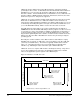
Table Of Contents
- S-3056-1 Distributed Power System SA3100 Drive Configuration and Programming Instruction Manual
- Important User Information
- Contents
- List of Figures
- List of Tables
- Chapter 1 Introduction
- Chapter 2 Configuring the UDC Module, Regulator Type, and Parameters
- 2.1 Adding a Universal Drive Controller (UDC) Module
- 2.2 Entering the Drive Parameters
- 2.3 Configuring the Vector with Constant Power Regulator
- 2.4 Configuring the Volts per Hertz (V/Hz) Regulator
- 2.5 Configuring Flex I/O
- 2.6 Generating Drive Parameter Files and Printing Drive Parameters
- Chapter 3 Configuring the UDC Module’s Registers
- 3.1 Register and Bit Reference Conventions Used in this Manual
- 3.2 Flex I/O Port Registers (Registers 0-23)
- 3.3 UDC/PMI Communication Status Registers (Registers 80-89/1080-1089)
- 3.4 Command Registers (Registers 100-199/1100-1199)
- 3.5 Feedback Registers (Registers 200-299/1200-1299)
- 3.6 Application Registers (Registers 300-599, Every Scan) (Registers 1300-1599, Every Nth Scan)
- 3.7 UDC Module Test I/O Registers (Registers 1000-1017)
- 3.8 Interrupt Status and Control Registers (Registers 2000-2047)
- Chapter 4 Application Programming for DPS Drive Control
- Chapter 5 On-Line Operation
- Appendix A SA3100 Vector Regulator Register Reference
- Appendix B SA3100 Volts / Hertz Regulator Register Reference
- Appendix C SA3100 Local Tunable Variables
- Appendix D Vector with Constant Power Regulator
- Appendix E Volts per Hertz (V/Hz) Regulator
- Appendix F Status of Data in the AutoMax Rack After a STOP_ALL Command or STOP_ALL Fault
- Appendix G Torque Overload Ratio Parameter Precautions
- Appendix H Default Carrier Frequency and Carrier Frequency Limit for Drive Horsepower Ranges
- Appendix I Vector with Constant Power Parameter Entry Example
- Index

Application Programming for DPS Drive Control
4-3
All common input values for the UDC task are first read from the dual port memory
and then stored in a local buffer in order to have a consistent context for evaluation.
The task is then executed. After the task has been executed, the common output
values from the UDC task are written from the local memory buffer to dual port
memory.
The only exception to this pattern are the common variables in the “Nth” scan
application register area. These registers are updated immediately before every “Nth”
scan only, as defined by the user. See section 4.3 and figure 4.3 for more information
on “Nth” scan interrupts. See section 4.2.3 for more information on the command and
feedback messages.
4.2.1 Typical Structure of a UDC Task
They typical structure of a UDC task is described in the following paragraphs. The
first part of the task, described in steps 1 to 4 below, is considered task initialization.
This part of the task will only run on the initial scan of the task or on any subsequent
re-start.
Step 1. Local and common variable definitions
This section of the task defines names for values internal to the task
(LOCALs) and all UDC dual port memory registers used in the task
(COMMONs).
Step 2. Pre-defined local tunable variable definitions
This section defines the variables that are used by the PMI for functions such
as tuning the control algorithm and calibrating the resolver. The UDC task
“skeleton” file in the Programming Executive software includes these local
tunable definitions. See section 4.2 and Appendix B for more information.
Step 3. Initialization
a. UDC Meter port set-up: The registers whose values will be output on the
UDC Meter Ports are defined here. These registers can also be defined
on-line using the Programming Executive software (optional).
b. Scans per update definition: The scans-per-update register (2001 for both
drive A and B) is defined to tell the UDC Processor when to update the Nth
scan registers, and optionally, also when to interrupt an AutoMax
Processor task that has defined a hardware EVENT tied to the UDC’s
interrupt register. The AutoMax task can then read from and write to the
UDC dual port memory registers, and coordinate with the other tasks in
the system (optional).
c. Any other initialization required for the application.
This portion of the task (steps 1 to 3), before the SCAN_LOOP block, only
executes the first time that the task is scanned, after a STOP ALL command
and subsequent Run command, or after power is recycled to the rack.