
Instruction Manual

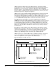
Table Of Contents
- S-3056-1 Distributed Power System SA3100 Drive Configuration and Programming Instruction Manual
- Important User Information
- Contents
- List of Figures
- List of Tables
- Chapter 1 Introduction
- Chapter 2 Configuring the UDC Module, Regulator Type, and Parameters
- 2.1 Adding a Universal Drive Controller (UDC) Module
- 2.2 Entering the Drive Parameters
- 2.3 Configuring the Vector with Constant Power Regulator
- 2.4 Configuring the Volts per Hertz (V/Hz) Regulator
- 2.5 Configuring Flex I/O
- 2.6 Generating Drive Parameter Files and Printing Drive Parameters
- Chapter 3 Configuring the UDC Module’s Registers
- 3.1 Register and Bit Reference Conventions Used in this Manual
- 3.2 Flex I/O Port Registers (Registers 0-23)
- 3.3 UDC/PMI Communication Status Registers (Registers 80-89/1080-1089)
- 3.4 Command Registers (Registers 100-199/1100-1199)
- 3.5 Feedback Registers (Registers 200-299/1200-1299)
- 3.6 Application Registers (Registers 300-599, Every Scan) (Registers 1300-1599, Every Nth Scan)
- 3.7 UDC Module Test I/O Registers (Registers 1000-1017)
- 3.8 Interrupt Status and Control Registers (Registers 2000-2047)
- Chapter 4 Application Programming for DPS Drive Control
- Chapter 5 On-Line Operation
- Appendix A SA3100 Vector Regulator Register Reference
- Appendix B SA3100 Volts / Hertz Regulator Register Reference
- Appendix C SA3100 Local Tunable Variables
- Appendix D Vector with Constant Power Regulator
- Appendix E Volts per Hertz (V/Hz) Regulator
- Appendix F Status of Data in the AutoMax Rack After a STOP_ALL Command or STOP_ALL Fault
- Appendix G Torque Overload Ratio Parameter Precautions
- Appendix H Default Carrier Frequency and Carrier Frequency Limit for Drive Horsepower Ranges
- Appendix I Vector with Constant Power Parameter Entry Example
- Index

4-4
SA3100 Drive Configuration and Programming
Step 4. SCAN_LOOP block/Enabling CCLK
This control block tells the UDC operating system how often to execute the
task based on the constant clock (CCLK) signal on the rack backplane. Note
that the CCLK signal must be enabled by a task in the rack before any UDC
tasks in the rack can be scanned beyond their SCAN_LOOP blocks. Note
that CCLK must be enabled again after a STOP ALL in the rack. CCLK is
enabled by setting the appropriate “CCLK enable” bit on certain modules in
the rack, such as the UDC module, CCLK must be enabled on one module
only. If CCLK is enabled on multiple modules in the rack, an overlap error
will result (error code 38).
The UDC task runs based on “ticks;” one tick is equal to one 500 ) CCLK
interval. The value can range from 1 to 20 ticks.
The programmer must specify how often the task should run in the TICKS
parameter of the SCAN_LOOP block in the task itself. The TICKS value
represents the number of 500 will occur. In order to calculate this value,
both drive A and drive B tasks must be considered together because they
execute one immediately following he other (A, then B). See figure 4.1 for
more information.
When determining the value to enter, the programmer must consider how
long it will take both tasks to actually run, allow some time for processing
overhead, and use the resulting value to determine the TICKS value for the
SCAN_LOOP block in both the drive A and drive B tasks. The AutoMax
Control Block Language manual (J-3676) lists the execution times of the
Control Blocks.
For example, if the programmer assigns UDC task A a TICKS parameter of 8
(4 msec), then UDC task B must also have TICKS defined at 8, and both
tasks must be able to execute within an 8 tick window of time, or an overlap
error will result and all tasks in the rack will stop. If the tick rates do not
match, error code 956 will be reported for one or both tasks in the error log;
and all tasks in the rack will be stopped.
Note that, unlike Control Block tasks on AutoMax Processors, UDC tasks
cannot run on a hardware or software event basis. The EVENT parameter
cannot be specified in the SCAN_LOOP block in UDC tasks. This means
that there is no time-out for execution of the UDC tasks. If the UDC task is
scanned to the SCAN_LOOP block and CCLK is not on, the task will simply
wait without timing out.
Note that no other control blocks are permitted before the SCAN_LOOP
block. BASIC statements, however, are permitted before the SCAN_LOOP
block.
Step 5. Other Control Block and BASIC statements or functions
This portion of the task consists of the logic specifically required for the
application. This portion of the UDC task (after the SCAN_LOOP block) is
the only part of the task that executes after the initial scan of the task, after a
STOP ALL command and subsequent Run command, or after power is
cycled to the rack.