
Instruction Manual

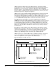
Table Of Contents
- S-3056-1 Distributed Power System SA3100 Drive Configuration and Programming Instruction Manual
- Important User Information
- Contents
- List of Figures
- List of Tables
- Chapter 1 Introduction
- Chapter 2 Configuring the UDC Module, Regulator Type, and Parameters
- 2.1 Adding a Universal Drive Controller (UDC) Module
- 2.2 Entering the Drive Parameters
- 2.3 Configuring the Vector with Constant Power Regulator
- 2.4 Configuring the Volts per Hertz (V/Hz) Regulator
- 2.5 Configuring Flex I/O
- 2.6 Generating Drive Parameter Files and Printing Drive Parameters
- Chapter 3 Configuring the UDC Module’s Registers
- 3.1 Register and Bit Reference Conventions Used in this Manual
- 3.2 Flex I/O Port Registers (Registers 0-23)
- 3.3 UDC/PMI Communication Status Registers (Registers 80-89/1080-1089)
- 3.4 Command Registers (Registers 100-199/1100-1199)
- 3.5 Feedback Registers (Registers 200-299/1200-1299)
- 3.6 Application Registers (Registers 300-599, Every Scan) (Registers 1300-1599, Every Nth Scan)
- 3.7 UDC Module Test I/O Registers (Registers 1000-1017)
- 3.8 Interrupt Status and Control Registers (Registers 2000-2047)
- Chapter 4 Application Programming for DPS Drive Control
- Chapter 5 On-Line Operation
- Appendix A SA3100 Vector Regulator Register Reference
- Appendix B SA3100 Volts / Hertz Regulator Register Reference
- Appendix C SA3100 Local Tunable Variables
- Appendix D Vector with Constant Power Regulator
- Appendix E Volts per Hertz (V/Hz) Regulator
- Appendix F Status of Data in the AutoMax Rack After a STOP_ALL Command or STOP_ALL Fault
- Appendix G Torque Overload Ratio Parameter Precautions
- Appendix H Default Carrier Frequency and Carrier Frequency Limit for Drive Horsepower Ranges
- Appendix I Vector with Constant Power Parameter Entry Example
- Index

Application Programming for DPS Drive Control
4-5
Step 6. Motor thermal overload protection
Electronic thermal overload protection for SA3100 drives is normally
provided by the THERMAL OVERLOAD block. The following briefly
describes how the THERMAL OVERLOAD block works, how to program the
block, and what adjustments are possible. Each UDC task must contain a
THERMAL OVERLOAD block, unless motor thermal overload protection is
provided by a hardware device. See J-3676, the Control Block Language
instruction manual, for the structure of the block.
The THERMAL OVERLOAD control block is used to create a model of the
temperature in a single device, such as a motor or power module, controlled
by a DPS drive and to turn on an alarm when an overload condition exists.
The block calculates a rise in temperature based on current feedback. When
operating above 100%, if the rise in temperature exceeds the programmed
limit, the OVERLOAD output will turn on. After the overload condition is
detected, the rise in temperature must return to the 100% or less condition
before the drive will be allowed to turn on again.
The operation of the block is programmed through four block input
parameters: LIM_BAR, THRESHOLD, TRIP_TIME, and I_FDBK. The value
used for LIM_BAR must be the same value entered as the motor overload
ratio during drive parameter configuration. The value used for THRESHOLD
selects the percent of full load current at which overload is detected. The
value used for TRIP_TIME selects the time, in seconds, within which the
block must detect an overload after a step from 100% current to LIM_BAR.
The main input to the THERMAL OVERLOAD block is I_FDBK. I_FDBK
represents current feedback from the PMI in counts (register 211/1211),
scaled so that LIM_BAR is 4095 counts.
The main output from the block is OVERLOAD. This boolean block will be
turned on when a thermal overload is detected. The OVERLOAD output
must be programmed in a Ladder Logic task to turn off the drive when the
fault is detected. The block also has an output called CALC_RISE. Current
feedback is squared, scaled, passed through a Lag filter, and then written to
CALC_RISE.
!
ATTENTION:Electronic motor overload protection must be provided for
each motor in a Distributed Power Drive application to protect the motor
against excessive heat caused by high currents. This protection can be
provided by either the THERMAL OVERLOAD software block or an
external hardware device. Applications in which a single power module
is controlling multiple motors cannot use the THERMAL OVERLOAD
software block and must use an external hardware device or devices to
provide this protection. Failure to observe this precaution could result in
damage to, or destruction of, the equipment.