
Instruction Manual

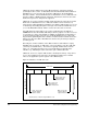
Table Of Contents
- S-3056-1 Distributed Power System SA3100 Drive Configuration and Programming Instruction Manual
- Important User Information
- Contents
- List of Figures
- List of Tables
- Chapter 1 Introduction
- Chapter 2 Configuring the UDC Module, Regulator Type, and Parameters
- 2.1 Adding a Universal Drive Controller (UDC) Module
- 2.2 Entering the Drive Parameters
- 2.3 Configuring the Vector with Constant Power Regulator
- 2.4 Configuring the Volts per Hertz (V/Hz) Regulator
- 2.5 Configuring Flex I/O
- 2.6 Generating Drive Parameter Files and Printing Drive Parameters
- Chapter 3 Configuring the UDC Module’s Registers
- 3.1 Register and Bit Reference Conventions Used in this Manual
- 3.2 Flex I/O Port Registers (Registers 0-23)
- 3.3 UDC/PMI Communication Status Registers (Registers 80-89/1080-1089)
- 3.4 Command Registers (Registers 100-199/1100-1199)
- 3.5 Feedback Registers (Registers 200-299/1200-1299)
- 3.6 Application Registers (Registers 300-599, Every Scan) (Registers 1300-1599, Every Nth Scan)
- 3.7 UDC Module Test I/O Registers (Registers 1000-1017)
- 3.8 Interrupt Status and Control Registers (Registers 2000-2047)
- Chapter 4 Application Programming for DPS Drive Control
- Chapter 5 On-Line Operation
- Appendix A SA3100 Vector Regulator Register Reference
- Appendix B SA3100 Volts / Hertz Regulator Register Reference
- Appendix C SA3100 Local Tunable Variables
- Appendix D Vector with Constant Power Regulator
- Appendix E Volts per Hertz (V/Hz) Regulator
- Appendix F Status of Data in the AutoMax Rack After a STOP_ALL Command or STOP_ALL Fault
- Appendix G Torque Overload Ratio Parameter Precautions
- Appendix H Default Carrier Frequency and Carrier Frequency Limit for Drive Horsepower Ranges
- Appendix I Vector with Constant Power Parameter Entry Example
- Index

4-6
SA3100 Drive Configuration and Programming
Consider an example in which LIM_BAR is defined to be 150% of full load
current, THRESHOLD is 114%, and TRIP_TIME is 60 seconds. When
I_FDBK is at 100%, CALC_RISE will reach a steady state value of 1000
(100
2
/ 10). With THRESHOLD at 114%, the trip point for CALC_RISE will
be 1300 (114
2
/ 10). If I_FDBK is at steady state (100%) and then is stepped
to 150%, CALC_RISE will integrate up to 1300 in 60 seconds and
OVERLOAD will turn on. The OVERLOAD output will stay on until the rise
decays to less than 1000. If I_FDBK remains less than 114%, CALC_RISE
will remain less than 1300 and OVERLOAD will not turn on.
The rate at which the CALC_RISE block parameter counts up and down is
calculated so that a step from 100% to LIM_BAR will turn on the OVERLOAD
in TRIP_TIME seconds. If current feedback steps from 100% to a value less
than current limit, it will take longer to detect the overload. If I_FDBK is
stepped from zero to LIM_BAR, the block will take approximately four times
the value of TRIP_TIME to detect the overload.
UL 508C section 56.1.3 specifies that when subjected to 200% of rated full
load motor current, the overload protection must trip in at least eight (8)
minutes. Because TRIP_TIME is calibrated from 100% to current limit, and
TRIP_TIME from zero to current limit is approximately four times longer, the
maximum trip time that is allowed is 2 minutes (120 seconds). To meet UL
listing requirements, any value greater than 120 seconds is internally limited
to 120 seconds.
The National Electric Code (430-32; 1993) requires that thermal overloads
protecting motors having a 1.0 service factor trip at load currents no greater
than 115% of full load. To meet NEC requirements, the THRESHOLD block
parameter has a default value of 114% and should not be set higher.
4.2.2 Local Tunable Variables
A set of local tunable variables with reserved (pre-defined) names is used to store
different types of values for use in drive control. For a description of the local tunable
variables used in SA3100 drives, refer to Appendix B.
All pre-defined local tunables must be defined in each UDC task (using the BASIC
language LOCAL statement) in order for the task to be loaded onto the UDC module.
Although all of these variables are not necessarily used in the UDC task itself, they
must be defined there in order to provide a mechanism for passing the values
between the UDC module and the PMI. For convenience, all these variables are
already defined in the UDC task “skeleton” file in the AutoMax Programming
Executive, with “HIGH,” “LOW,” “STEP,” and “CURRENT” values.
Your application task must define these variables using the same “HIGH,” “LOW,” and
“STEP” limit values as the ones found in the skeleton task. Note that you can only
change the “CURRENT” value in the application task. If the UDC operating system
needs to clamp a value at the higher or lower limit, it changes the actual value in the
task and writes error code 958 into the error log for the task.
The local tunable values can be modified through the application task on the UDC
module and by the operator using the Monitor function. See the BASIC language
instruction manual, J-3675, for more information on local tunable variables and the
WRITE_TUNE statement. Local tunable variables cannot be forced.