
Instruction Manual

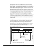
Table Of Contents
- S-3056-1 Distributed Power System SA3100 Drive Configuration and Programming Instruction Manual
- Important User Information
- Contents
- List of Figures
- List of Tables
- Chapter 1 Introduction
- Chapter 2 Configuring the UDC Module, Regulator Type, and Parameters
- 2.1 Adding a Universal Drive Controller (UDC) Module
- 2.2 Entering the Drive Parameters
- 2.3 Configuring the Vector with Constant Power Regulator
- 2.4 Configuring the Volts per Hertz (V/Hz) Regulator
- 2.5 Configuring Flex I/O
- 2.6 Generating Drive Parameter Files and Printing Drive Parameters
- Chapter 3 Configuring the UDC Module’s Registers
- 3.1 Register and Bit Reference Conventions Used in this Manual
- 3.2 Flex I/O Port Registers (Registers 0-23)
- 3.3 UDC/PMI Communication Status Registers (Registers 80-89/1080-1089)
- 3.4 Command Registers (Registers 100-199/1100-1199)
- 3.5 Feedback Registers (Registers 200-299/1200-1299)
- 3.6 Application Registers (Registers 300-599, Every Scan) (Registers 1300-1599, Every Nth Scan)
- 3.7 UDC Module Test I/O Registers (Registers 1000-1017)
- 3.8 Interrupt Status and Control Registers (Registers 2000-2047)
- Chapter 4 Application Programming for DPS Drive Control
- Chapter 5 On-Line Operation
- Appendix A SA3100 Vector Regulator Register Reference
- Appendix B SA3100 Volts / Hertz Regulator Register Reference
- Appendix C SA3100 Local Tunable Variables
- Appendix D Vector with Constant Power Regulator
- Appendix E Volts per Hertz (V/Hz) Regulator
- Appendix F Status of Data in the AutoMax Rack After a STOP_ALL Command or STOP_ALL Fault
- Appendix G Torque Overload Ratio Parameter Precautions
- Appendix H Default Carrier Frequency and Carrier Frequency Limit for Drive Horsepower Ranges
- Appendix I Vector with Constant Power Parameter Entry Example
- Index

Application Programming for DPS Drive Control
4-7
Like all tunable values in the AutoMax environment, the values of these UDC task
tunables are retained through a power loss. Note that the programmer can also
define other local tunable variables for application-specific purposes, but that the total
number of all local tunables in a UDC task cannot exceed 127.
4.2.2.1 Calculating Local Tunable Values
Depending upon the type of local tunable variable, the “CURRENT” value, i.e., the
value to be used for the next scan of the PMI, can be determined in one of the
following ways:
1. Self Tune.
The programmer can request the PMI to generate the values for some of the
variables. For example, the programmer can set the resolver calibration command
bit in register 101/1101 to cause the PMI to adjust the resolver balance.
When the PMI has generated the values, it sends them to the UDC module over
the fiber-optic link. The UDC module stores the values in the corresponding
tunable variables. A copy of these values is maintained in the PMI for use in the
execution of the control algorithm.
2. Tune values from the Programming Executive software and tasks.
The Monitor function in the Programming Executive allows all local tunables to be
modified on-line within the limits defined in the LOCAL statement in the UDC task.
Note that this is not recommended for the resolver calibration values because
these values can be generated more precisely by the PMI during auto-tuning. At
the end of the UDC task scan, the new values are sent to the PMI to be used in
the execution of the control algorithm.
3. Enter the desired value into the “CURRENT” field for each LOCAL statement.
The programmer can choose to enter the desired values for local tunables in the
“CURRENT” field of the corresponding LOCAL statement or leave them
unchanged.
4.2.3 UDC/PMI Task Communication
Coordination between the two PMIs running their respective PMI tasks (drives A and
B) and the UDC module running the corresponding UDC tasks is managed through
the command and feedback messages sent over the fiber-optic link. The programmer
does not control the operating system on the PMI. The timing of the PMI is based on
the regulator selected.
A command message is sent to the PMI by the UDC module at the end of every scan
of the UDC task. Each message contains the data in registers 100-106/1100-1106,
Flex I/O data, and the values of the pre-defined local tunables that have changed.
Note that some data may be sent over the course of several command messages.
A feedback message is sent to the UDC module by the PMI immediately before the
beginning of every scan of the UDC task, i.e., immediately before the CCLK timer
expires. Each message contains the data for registers 200-221/1200-1221, as well as
any Flex I/O data that has changed from the last feedback message.