
Instruction Manual

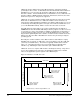
Table Of Contents
- S-3056-1 Distributed Power System SA3100 Drive Configuration and Programming Instruction Manual
- Important User Information
- Contents
- List of Figures
- List of Tables
- Chapter 1 Introduction
- Chapter 2 Configuring the UDC Module, Regulator Type, and Parameters
- 2.1 Adding a Universal Drive Controller (UDC) Module
- 2.2 Entering the Drive Parameters
- 2.3 Configuring the Vector with Constant Power Regulator
- 2.4 Configuring the Volts per Hertz (V/Hz) Regulator
- 2.5 Configuring Flex I/O
- 2.6 Generating Drive Parameter Files and Printing Drive Parameters
- Chapter 3 Configuring the UDC Module’s Registers
- 3.1 Register and Bit Reference Conventions Used in this Manual
- 3.2 Flex I/O Port Registers (Registers 0-23)
- 3.3 UDC/PMI Communication Status Registers (Registers 80-89/1080-1089)
- 3.4 Command Registers (Registers 100-199/1100-1199)
- 3.5 Feedback Registers (Registers 200-299/1200-1299)
- 3.6 Application Registers (Registers 300-599, Every Scan) (Registers 1300-1599, Every Nth Scan)
- 3.7 UDC Module Test I/O Registers (Registers 1000-1017)
- 3.8 Interrupt Status and Control Registers (Registers 2000-2047)
- Chapter 4 Application Programming for DPS Drive Control
- Chapter 5 On-Line Operation
- Appendix A SA3100 Vector Regulator Register Reference
- Appendix B SA3100 Volts / Hertz Regulator Register Reference
- Appendix C SA3100 Local Tunable Variables
- Appendix D Vector with Constant Power Regulator
- Appendix E Volts per Hertz (V/Hz) Regulator
- Appendix F Status of Data in the AutoMax Rack After a STOP_ALL Command or STOP_ALL Fault
- Appendix G Torque Overload Ratio Parameter Precautions
- Appendix H Default Carrier Frequency and Carrier Frequency Limit for Drive Horsepower Ranges
- Appendix I Vector with Constant Power Parameter Entry Example
- Index

4-8
SA3100 Drive Configuration and Programming
The exchange of command and feedback register data is synchronized through the
use of the constant clock signal (CCLK) on the UDC module as described below.
CCLK also enables the coordination of all UDCs in a rack because they will all use the
same time base for task execution. Note that all UDC modules in a rack are not
required to have the same value in the TICKS parameter of the SCAN_LOOP block in
both their tasks. In other words, if the UDC module in slot 6 has TICKS = 10 in its
tasks, and the UDC module in slot 7 has TICKS = 20 in its tasks, the tasks on the UDC
module in slot 6 will execute twice as often as the tasks on the UDC module in slot 7,
but they will execute on the same time basis, i.e., time zero is determined by CCLK
timer expiration.
As soon as the UDC module and PMI are connected over the fiber-optic link, the PMI
will request its operating system from the UDC module. Recall that the PMI operating
system is part of the UDC operating system. As long as the UDC module has its own
operating system and parameter object file, it will download to the PMI the correct
operating system.
In order for the PMI and the UDC module to be synchronized, the UDC module must
have its operating system, parameter object file, and configuration loaded. In
addition, CCLK must be turned on in the AutoMax rack.
If the UDC tasks are already loaded onto the UDC module when the PMI requests its
operating system, the UDC module will also send information about when the PMI
should send feedback register data required by the UDC task(s). This ensures that
the data is measured or calculated as close as possible to the time it is needed in
order to ensure it is as current as possible for the next scan of the UDC task(s).
The UDC operating system determines the feedback register message timing
required by examining the SCAN_LOOP block in each UDC task so that the feedback
will arrive at the UDC module just before it is needed. For example, if the TICKS
parameter value in the SCAN_LOOP block were 10, feedback data would be needed
by the UDC module immediately before 10 x 500 µsec time expires.
At first, when the UDC module and PMI(s) are powered up and connected via the
fiber-optic link, their system clocks are not synchronized. In order for the PMI and
UDC module to be synchronized to the same clock signal for communicating
command and feedback data on a regular and predictable basis, an AutoMax task
must turn on the CCLK signal in the rack. Until CCLK is turned on, command and
feedback messages are sent periodically, but not on a predictable basis.
CCLK can be turned on by setting the appropriate bit in UDC register 2000 (the
interrupt status and control register for both A and B drive tasks), or by setting a bit in
another module that can turn on CCLK. Only one module in the rack must turn on
CCLK. Note that after a STOP ALL occurs in the rack, CCLK will be disabled and must
be re-enabled again in order for UDC tasks to go into run. See figure 4.3 at the end of
this chapter for the typical data flow between the UDC module and the PMI.
To verify that communication between the UDC module and the PMI is resulting in up-
to-date feedback data, it is recommended that the drive’s run permissive logic include
the CCLK synchronized status bit (register 200/1200, bit 14, CCLK_OK@) and the
communication lost fault bit (register 202/1202, bit 15, FLT_COM@) as shown in
figure 4.2.