
Instruction Manual
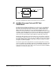

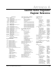
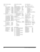
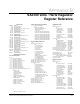

Table Of Contents
- S-3056-1 Distributed Power System SA3100 Drive Configuration and Programming Instruction Manual
- Important User Information
- Contents
- List of Figures
- List of Tables
- Chapter 1 Introduction
- Chapter 2 Configuring the UDC Module, Regulator Type, and Parameters
- 2.1 Adding a Universal Drive Controller (UDC) Module
- 2.2 Entering the Drive Parameters
- 2.3 Configuring the Vector with Constant Power Regulator
- 2.4 Configuring the Volts per Hertz (V/Hz) Regulator
- 2.5 Configuring Flex I/O
- 2.6 Generating Drive Parameter Files and Printing Drive Parameters
- Chapter 3 Configuring the UDC Module’s Registers
- 3.1 Register and Bit Reference Conventions Used in this Manual
- 3.2 Flex I/O Port Registers (Registers 0-23)
- 3.3 UDC/PMI Communication Status Registers (Registers 80-89/1080-1089)
- 3.4 Command Registers (Registers 100-199/1100-1199)
- 3.5 Feedback Registers (Registers 200-299/1200-1299)
- 3.6 Application Registers (Registers 300-599, Every Scan) (Registers 1300-1599, Every Nth Scan)
- 3.7 UDC Module Test I/O Registers (Registers 1000-1017)
- 3.8 Interrupt Status and Control Registers (Registers 2000-2047)
- Chapter 4 Application Programming for DPS Drive Control
- Chapter 5 On-Line Operation
- Appendix A SA3100 Vector Regulator Register Reference
- Appendix B SA3100 Volts / Hertz Regulator Register Reference
- Appendix C SA3100 Local Tunable Variables
- Appendix D Vector with Constant Power Regulator
- Appendix E Volts per Hertz (V/Hz) Regulator
- Appendix F Status of Data in the AutoMax Rack After a STOP_ALL Command or STOP_ALL Fault
- Appendix G Torque Overload Ratio Parameter Precautions
- Appendix H Default Carrier Frequency and Carrier Frequency Limit for Drive Horsepower Ranges
- Appendix I Vector with Constant Power Parameter Entry Example
- Index
Application Programming for DPS Drive Control
4-9
Refer to the individual bit descriptions in this manual for more information.
4.3 AutoMax Processor Task and UDC Task
Coordination
Recall that all tasks running on AutoMax Processors have access to the UDC dual
port registers, but that UDC tasks can only access those common variables that
represent registers in their own dual port memory. Task coordination between the
UDC module and the AutoMax Processor is generally handled through periodic
hardware interrupts generated by the UDC module. An AutoMax task needs to define
a hardware “event” that will trigger some action by an AutoMax task, using the BASIC
statement EVENT. The EVENT statement must reference the hardware interrupt
status and control register ISCR% (register 2000 in the UDC dual port memory).
Although the UDC operating system itself actually causes the interrupt, a task in the
rack (AutoMax or UDC) must write to the scans per update register in the UDC dual
port (register 2001) in order to define the number of UDC task scans between updates
of the Nth scan application registers (1300-1599), and between hardware interrupts.
See figure 3.2 for more information.
Note that the register values being latched on every Nth scan provide a consistent
context for evaluation of Control Block statements, but that BASIC statements in UDC
tasks read and write data immediately: that is, they do not read from and write to a
local buffer. Referencing the same common values in both Control Block and BASIC
statements in one task can result in errors.
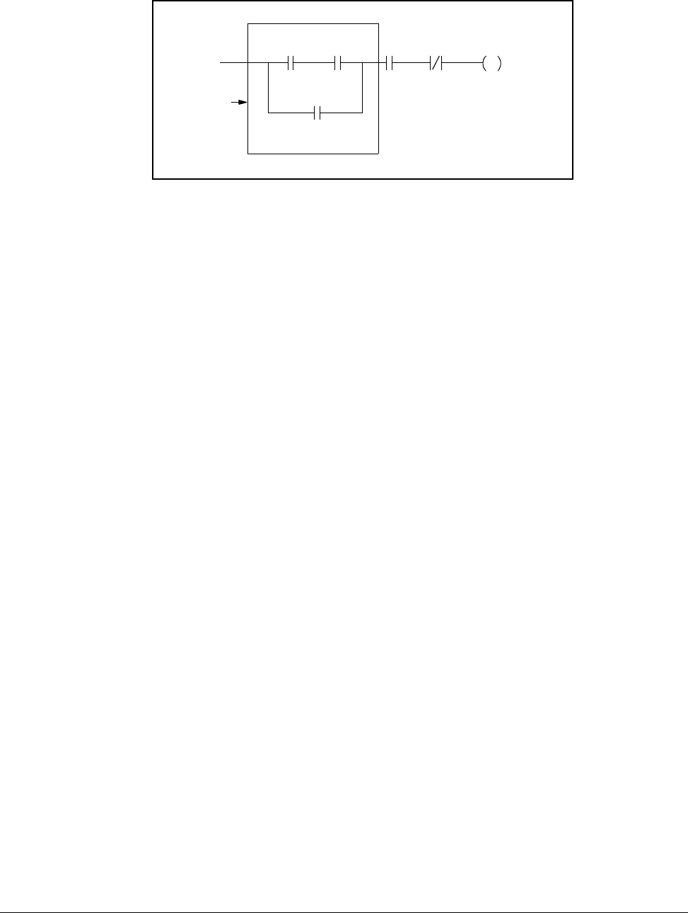
Figure 4.2 – Recommended Run Permissive Logic
CCLK_OK@ COM_FLT@ RUN_PERM@
RUN_PERM@
Start
Permissive
Logic