
Instruction Manual
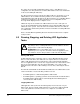

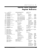
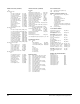
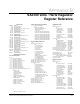

Table Of Contents
- S-3056-1 Distributed Power System SA3100 Drive Configuration and Programming Instruction Manual
- Important User Information
- Contents
- List of Figures
- List of Tables
- Chapter 1 Introduction
- Chapter 2 Configuring the UDC Module, Regulator Type, and Parameters
- 2.1 Adding a Universal Drive Controller (UDC) Module
- 2.2 Entering the Drive Parameters
- 2.3 Configuring the Vector with Constant Power Regulator
- 2.4 Configuring the Volts per Hertz (V/Hz) Regulator
- 2.5 Configuring Flex I/O
- 2.6 Generating Drive Parameter Files and Printing Drive Parameters
- Chapter 3 Configuring the UDC Module’s Registers
- 3.1 Register and Bit Reference Conventions Used in this Manual
- 3.2 Flex I/O Port Registers (Registers 0-23)
- 3.3 UDC/PMI Communication Status Registers (Registers 80-89/1080-1089)
- 3.4 Command Registers (Registers 100-199/1100-1199)
- 3.5 Feedback Registers (Registers 200-299/1200-1299)
- 3.6 Application Registers (Registers 300-599, Every Scan) (Registers 1300-1599, Every Nth Scan)
- 3.7 UDC Module Test I/O Registers (Registers 1000-1017)
- 3.8 Interrupt Status and Control Registers (Registers 2000-2047)
- Chapter 4 Application Programming for DPS Drive Control
- Chapter 5 On-Line Operation
- Appendix A SA3100 Vector Regulator Register Reference
- Appendix B SA3100 Volts / Hertz Regulator Register Reference
- Appendix C SA3100 Local Tunable Variables
- Appendix D Vector with Constant Power Regulator
- Appendix E Volts per Hertz (V/Hz) Regulator
- Appendix F Status of Data in the AutoMax Rack After a STOP_ALL Command or STOP_ALL Fault
- Appendix G Torque Overload Ratio Parameter Precautions
- Appendix H Default Carrier Frequency and Carrier Frequency Limit for Drive Horsepower Ranges
- Appendix I Vector with Constant Power Parameter Entry Example
- Index

On-Line Operation
5-3
Deleting UDC Tasks
When a UDC application task is deleted, any local variables which were forced are
removed from the force table. The task’s error log is also cleared.
5.4 UDC Information Log and Error Log
The information log and error log for a UDC task can be displayed by selecting “I” for
Info/Log from the ON LINE menu. Refer to the AutoMax Programming Executive
instruction manual for the procedure.
The information log for a slot containing a UDC module will display the UDC operating
system’s part number, the utilization of the CPU resources in the UDC module, and
various memory and PMI rack statistics. Select “U” from the Info/Log menu to display
the information log. Note that the UDC module’s CPU utilization should not exceed
75%.
Like AutoMax tasks, UDC tasks can access the error log by using the BASIC
statement CLR_ERRLOG@ and BASIC function TST_ERRLOG@. The error log will
display the first, second, and last errors and will maintain them until power is cycled.