
Instruction Manual


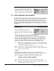
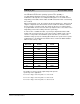
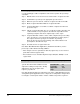
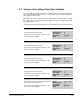
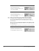
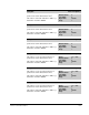
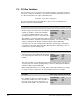
Table Of Contents
- S-3056-1 Distributed Power System SA3100 Drive Configuration and Programming Instruction Manual
- Important User Information
- Contents
- List of Figures
- List of Tables
- Chapter 1 Introduction
- Chapter 2 Configuring the UDC Module, Regulator Type, and Parameters
- 2.1 Adding a Universal Drive Controller (UDC) Module
- 2.2 Entering the Drive Parameters
- 2.3 Configuring the Vector with Constant Power Regulator
- 2.4 Configuring the Volts per Hertz (V/Hz) Regulator
- 2.5 Configuring Flex I/O
- 2.6 Generating Drive Parameter Files and Printing Drive Parameters
- Chapter 3 Configuring the UDC Module’s Registers
- 3.1 Register and Bit Reference Conventions Used in this Manual
- 3.2 Flex I/O Port Registers (Registers 0-23)
- 3.3 UDC/PMI Communication Status Registers (Registers 80-89/1080-1089)
- 3.4 Command Registers (Registers 100-199/1100-1199)
- 3.5 Feedback Registers (Registers 200-299/1200-1299)
- 3.6 Application Registers (Registers 300-599, Every Scan) (Registers 1300-1599, Every Nth Scan)
- 3.7 UDC Module Test I/O Registers (Registers 1000-1017)
- 3.8 Interrupt Status and Control Registers (Registers 2000-2047)
- Chapter 4 Application Programming for DPS Drive Control
- Chapter 5 On-Line Operation
- Appendix A SA3100 Vector Regulator Register Reference
- Appendix B SA3100 Volts / Hertz Regulator Register Reference
- Appendix C SA3100 Local Tunable Variables
- Appendix D Vector with Constant Power Regulator
- Appendix E Volts per Hertz (V/Hz) Regulator
- Appendix F Status of Data in the AutoMax Rack After a STOP_ALL Command or STOP_ALL Fault
- Appendix G Torque Overload Ratio Parameter Precautions
- Appendix H Default Carrier Frequency and Carrier Frequency Limit for Drive Horsepower Ranges
- Appendix I Vector with Constant Power Parameter Entry Example
- Index

SA3100 Local Tunable Variables
C-1
APPENDIX C
SA3100 Local Tunable
Variables
C.1 Current Minor Loop Gain Variables
The stator resistance and the stator time constant values can be generated
automatically by using the enable tuning command (register 100/1100, bit 1). The
values generated by the system should not require adjustment. If any of these values
are modified outside of acceptable limits, the new value will be ignored and the last
acceptable value entered will be used. Bit 8 in warning register 203/1203 will also be
set to indicate the value entered was invalid.
CML_WCO% Current Minor Loop Crossover Frequency
The value of the Current Minor Loop Crossover
Frequency sets the desired response of the
current minor loop. The higher the value, the
more quickly the drive responds to a change in
torque reference current.
Units: Rads/Sec
Default Value: 1000
Low Limit: 1000
High Limit: 4000
Step: 1
This value is entered in radians per second. Note that if this value is adjusted too
high, the current minor loop will become unstable.
FLX_WCO% Flux Loop Crossover Frequency
The value of the Flux Loop Crossover
Frequency is used to adjust the bandwidth of
the flux loop used in the Constant Power
version of the SA3100 Vector regulator.
Units: Rads/Sec
Default Value: 10
Low Limit: 5
High Limit: 50
Step: 1
The value is entered in radians per second, where 1 = 1 radian/second.
STATOR_R_E4% Stator Resistance
The value of the Stator Resistance is used to
adjust the gain of the current minor loop. It is
also used in flux feedback calculations.
The value is entered in ohms times 10000, e.g.,
a resistance of 0.1 ohm is entered as 1000.
Units: Ohms ∗ 10000
Default Value: 10
Low Limit: 0
High Limit: 20000
Step: 1