
Instruction Manual


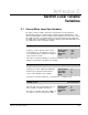
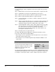
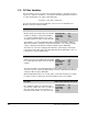
Table Of Contents
- S-3056-1 Distributed Power System SA3100 Drive Configuration and Programming Instruction Manual
- Important User Information
- Contents
- List of Figures
- List of Tables
- Chapter 1 Introduction
- Chapter 2 Configuring the UDC Module, Regulator Type, and Parameters
- 2.1 Adding a Universal Drive Controller (UDC) Module
- 2.2 Entering the Drive Parameters
- 2.3 Configuring the Vector with Constant Power Regulator
- 2.4 Configuring the Volts per Hertz (V/Hz) Regulator
- 2.5 Configuring Flex I/O
- 2.6 Generating Drive Parameter Files and Printing Drive Parameters
- Chapter 3 Configuring the UDC Module’s Registers
- 3.1 Register and Bit Reference Conventions Used in this Manual
- 3.2 Flex I/O Port Registers (Registers 0-23)
- 3.3 UDC/PMI Communication Status Registers (Registers 80-89/1080-1089)
- 3.4 Command Registers (Registers 100-199/1100-1199)
- 3.5 Feedback Registers (Registers 200-299/1200-1299)
- 3.6 Application Registers (Registers 300-599, Every Scan) (Registers 1300-1599, Every Nth Scan)
- 3.7 UDC Module Test I/O Registers (Registers 1000-1017)
- 3.8 Interrupt Status and Control Registers (Registers 2000-2047)
- Chapter 4 Application Programming for DPS Drive Control
- Chapter 5 On-Line Operation
- Appendix A SA3100 Vector Regulator Register Reference
- Appendix B SA3100 Volts / Hertz Regulator Register Reference
- Appendix C SA3100 Local Tunable Variables
- Appendix D Vector with Constant Power Regulator
- Appendix E Volts per Hertz (V/Hz) Regulator
- Appendix F Status of Data in the AutoMax Rack After a STOP_ALL Command or STOP_ALL Fault
- Appendix G Torque Overload Ratio Parameter Precautions
- Appendix H Default Carrier Frequency and Carrier Frequency Limit for Drive Horsepower Ranges
- Appendix I Vector with Constant Power Parameter Entry Example
- Index

SA3100 Local Tunable Variables
C-3
Tuning STATOR_IZ_E1% for Constant Power Applications
The SA3100 Constant Power operating system has the capability of
accommodating temperature changes via modification of the slip value. This
modification of the slip value is accomplished through the use of a PMI reference
magnetizing current table, which enables the PMI to determine when a load change
has occurred.
When a load change occurs, the output of the flux loop will increase. This increased
output is compared to the value from the reference table. The difference between
the two generates a change in slip. The change in slip causes a reduction in flux
loop output which, in turn, causes the flux loop output to be the correct value for the
magnetizing current value at that point in the speed range.
In order to tune or calibrate the table, a speed loop is implemented in the UDC
module. This speed loop must be set up so that a value of 4095 counts of speed
reference corresponds to the maximum speed of the drive (i.e. four times the
maximum voltage speed). The following table indicates the speed reference points
at which data is to be obtained: Note that the values saved in the IGNn! variables
will be in units of amps
∗
100.
Ref. Point
Speed Reference
Counts
Where the Value is
Saved
One 409 STATOR_IZ_E1%
Two
1023
1
1. Equal to maximum voltage speed.
The number of reference points required depends upon the
speed range of the application:
For a 2 to 1 range, reference points 1 to 7 are used.
For a 3 to 1 range, reference points 1 to 9 are used.
For a 4 to 1 range, reference points 1 to 10 are used.
IGN1!
Three 1125 IGN2!
Four 1227 IGN3!
Five 1329 IGN4!
Six 1635 IGN5!
Seven 1941 IGN6!
Eight 2247 IGN7!
Nine 2859 IGN8!
Ten 4095 IGN9!
STATOR_IZ_E1% No Load Stator Current