
Instruction Manual


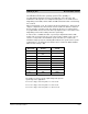
Table Of Contents
- S-3056-1 Distributed Power System SA3100 Drive Configuration and Programming Instruction Manual
- Important User Information
- Contents
- List of Figures
- List of Tables
- Chapter 1 Introduction
- Chapter 2 Configuring the UDC Module, Regulator Type, and Parameters
- 2.1 Adding a Universal Drive Controller (UDC) Module
- 2.2 Entering the Drive Parameters
- 2.3 Configuring the Vector with Constant Power Regulator
- 2.4 Configuring the Volts per Hertz (V/Hz) Regulator
- 2.5 Configuring Flex I/O
- 2.6 Generating Drive Parameter Files and Printing Drive Parameters
- Chapter 3 Configuring the UDC Module’s Registers
- 3.1 Register and Bit Reference Conventions Used in this Manual
- 3.2 Flex I/O Port Registers (Registers 0-23)
- 3.3 UDC/PMI Communication Status Registers (Registers 80-89/1080-1089)
- 3.4 Command Registers (Registers 100-199/1100-1199)
- 3.5 Feedback Registers (Registers 200-299/1200-1299)
- 3.6 Application Registers (Registers 300-599, Every Scan) (Registers 1300-1599, Every Nth Scan)
- 3.7 UDC Module Test I/O Registers (Registers 1000-1017)
- 3.8 Interrupt Status and Control Registers (Registers 2000-2047)
- Chapter 4 Application Programming for DPS Drive Control
- Chapter 5 On-Line Operation
- Appendix A SA3100 Vector Regulator Register Reference
- Appendix B SA3100 Volts / Hertz Regulator Register Reference
- Appendix C SA3100 Local Tunable Variables
- Appendix D Vector with Constant Power Regulator
- Appendix E Volts per Hertz (V/Hz) Regulator
- Appendix F Status of Data in the AutoMax Rack After a STOP_ALL Command or STOP_ALL Fault
- Appendix G Torque Overload Ratio Parameter Precautions
- Appendix H Default Carrier Frequency and Carrier Frequency Limit for Drive Horsepower Ranges
- Appendix I Vector with Constant Power Parameter Entry Example
- Index

C-4
SA3100 Drive Configuration and Programming
STATOR_IZ_E1% (continued) No Load Stator Current
Use the following procedure to implement each reference point in the speed loop
calculation:
Step 1. With the drive’s motor unconnected, set bits 0 and 1 of register 101/1101.
Step 2. Command the speed loop to the appropriate speed reference
Step 3. When the speed is reached, set bit 10 of register 101/1101 in the UDC.
Step 4. Monitor register 203/1203 and bit 10 of register 201/1201.
Step 5. If register 203/1203 is set to 20H, reset bit 10 of register 101/1101 and
proceed to step 7.
Step 6. If bit 10 of register 201/1201 was set, reset bit 10 in register 101/1101 and
continue with the next speed point as described in step 3. When all the
required speed points have been completed, proceed to step 8.
Step 7. If register 203/1203 contains a value of 20H, verify that the speed scaling
of the speed loop is correct and lower the initial value of Stator_IZ_E1%.
The output of the flux loop may be in saturation. Try lowering
Stator_IZ_E1% by 5%. Reset the warning, and continue with the next
speed point as described in step 3.
Step 8. Reset bits 0 and 1 of register 101/1101.
Note that in Dual Wound Motor Applications (Parallel Inverter Drives) use the
previous procedure with the following additions:
• After using the reference point data for drive A (register 101), use the reference
point data for drive B (register 1101).
• Ensure that the vector orientation alignment request bit (bit 6, 0040H) is set in
register 1100.
SLIP_ADJ_E3% Slip Adjustment
Rotor slip is calculated automatically by the
system. The value in this variable is used to
adjust the resulting rotor slip value. As Slip
Adjustment is increased, higher stator
frequency is produced.
Units: Gain
∗
1000
Default Value: 850
Low Limit: 500
High Limit: 1500
Step: 1
Note that slip will vary with rotor temperature. The value of Slip Adjustment may be
changed through an application task to compensate for temperature changes when
not using the constant power feature. A value of 1000 corresponds to a gain of 1.