
Instruction Manual
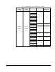
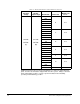
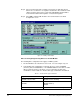
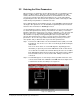
Table Of Contents
- S-3056-1 Distributed Power System SA3100 Drive Configuration and Programming Instruction Manual
- Important User Information
- Contents
- List of Figures
- List of Tables
- Chapter 1 Introduction
- Chapter 2 Configuring the UDC Module, Regulator Type, and Parameters
- 2.1 Adding a Universal Drive Controller (UDC) Module
- 2.2 Entering the Drive Parameters
- 2.3 Configuring the Vector with Constant Power Regulator
- 2.4 Configuring the Volts per Hertz (V/Hz) Regulator
- 2.5 Configuring Flex I/O
- 2.6 Generating Drive Parameter Files and Printing Drive Parameters
- Chapter 3 Configuring the UDC Module’s Registers
- 3.1 Register and Bit Reference Conventions Used in this Manual
- 3.2 Flex I/O Port Registers (Registers 0-23)
- 3.3 UDC/PMI Communication Status Registers (Registers 80-89/1080-1089)
- 3.4 Command Registers (Registers 100-199/1100-1199)
- 3.5 Feedback Registers (Registers 200-299/1200-1299)
- 3.6 Application Registers (Registers 300-599, Every Scan) (Registers 1300-1599, Every Nth Scan)
- 3.7 UDC Module Test I/O Registers (Registers 1000-1017)
- 3.8 Interrupt Status and Control Registers (Registers 2000-2047)
- Chapter 4 Application Programming for DPS Drive Control
- Chapter 5 On-Line Operation
- Appendix A SA3100 Vector Regulator Register Reference
- Appendix B SA3100 Volts / Hertz Regulator Register Reference
- Appendix C SA3100 Local Tunable Variables
- Appendix D Vector with Constant Power Regulator
- Appendix E Volts per Hertz (V/Hz) Regulator
- Appendix F Status of Data in the AutoMax Rack After a STOP_ALL Command or STOP_ALL Fault
- Appendix G Torque Overload Ratio Parameter Precautions
- Appendix H Default Carrier Frequency and Carrier Frequency Limit for Drive Horsepower Ranges
- Appendix I Vector with Constant Power Parameter Entry Example
- Index
Configuring the UDC Module, Regulator Type, and Parameters
2-1
CHAPTER 2
Configuring the UDC Module,
Regulator Type, and Parameters
The Rack Configurator application in the AutoMax Programming Executive is used to
configure the modules in a rack. Using the Rack Configurator, you create a graphical
representation of the actual modules in the rack. See the AutoMax Programming
Executive instruction manual for more information on configuring racks.
You can access the Rack Configurator by selecting the Configure Rack option from
the Rack menu of the System Configurator. An empty AutoMax rack will be displayed
initially.
2.1 Adding a Universal Drive Controller (UDC) Module
The UDC module may be placed in any slot in an AutoMax rack that contains at least
one AutoMax processor module (M/N 57C430A, 57C431, or 57C435). Note that the
UDC module cannot be used in a remote I/O rack. The rack does not require a
Common Memory module (M/N 57C413 or 57C423) unless more than one AutoMax
Processor is being used. A rack may contain up to ten UDC modules.
Some AutoMax modules,e.g., the Common Memory module and the Ethernet©
Interface module, may have an effect on the slot allocation in the rack that limits
where other modules may be inserted. See the appropriate instruction manual for
additional information. A UDC module may also be placed in a rack containing a set
of the AutoMax drive controller modules (B/M57401, 57405, 57406, and 57408).
Use the following procedure to add a UDC module to a rack. Refer to figure 2.1.
Step 1. Select an empty slot in the rack.
Step 2. Select Add from the Configure menu. A dialog box listing the available
modules will be displayed on the screen.
Step 3. Select the UDC module.
!
ATTENTION:Only qualified personnel familiar with the construction and
operation of this equipment and the hazards involved should install,
adjust, operate, or service this equipment. Read and understand this
manual and other applicable manuals in their entirety before proceeding.
Failure to observe this precaution could result in severe bodily injury or
loss of life.
ATTENTION:Only qualified Rockwell personnel or other trained
personnel who understand the potential hazards involved may make
modifications to the rack configuration. Any modifications may result in
uncontrolled machine operation. Failure to observe this precaution may
result in damage to equipment and bodily injury.