
Instruction Manual


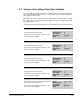
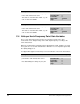
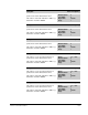
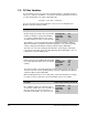
Table Of Contents
- S-3056-1 Distributed Power System SA3100 Drive Configuration and Programming Instruction Manual
- Important User Information
- Contents
- List of Figures
- List of Tables
- Chapter 1 Introduction
- Chapter 2 Configuring the UDC Module, Regulator Type, and Parameters
- 2.1 Adding a Universal Drive Controller (UDC) Module
- 2.2 Entering the Drive Parameters
- 2.3 Configuring the Vector with Constant Power Regulator
- 2.4 Configuring the Volts per Hertz (V/Hz) Regulator
- 2.5 Configuring Flex I/O
- 2.6 Generating Drive Parameter Files and Printing Drive Parameters
- Chapter 3 Configuring the UDC Module’s Registers
- 3.1 Register and Bit Reference Conventions Used in this Manual
- 3.2 Flex I/O Port Registers (Registers 0-23)
- 3.3 UDC/PMI Communication Status Registers (Registers 80-89/1080-1089)
- 3.4 Command Registers (Registers 100-199/1100-1199)
- 3.5 Feedback Registers (Registers 200-299/1200-1299)
- 3.6 Application Registers (Registers 300-599, Every Scan) (Registers 1300-1599, Every Nth Scan)
- 3.7 UDC Module Test I/O Registers (Registers 1000-1017)
- 3.8 Interrupt Status and Control Registers (Registers 2000-2047)
- Chapter 4 Application Programming for DPS Drive Control
- Chapter 5 On-Line Operation
- Appendix A SA3100 Vector Regulator Register Reference
- Appendix B SA3100 Volts / Hertz Regulator Register Reference
- Appendix C SA3100 Local Tunable Variables
- Appendix D Vector with Constant Power Regulator
- Appendix E Volts per Hertz (V/Hz) Regulator
- Appendix F Status of Data in the AutoMax Rack After a STOP_ALL Command or STOP_ALL Fault
- Appendix G Torque Overload Ratio Parameter Precautions
- Appendix H Default Carrier Frequency and Carrier Frequency Limit for Drive Horsepower Ranges
- Appendix I Vector with Constant Power Parameter Entry Example
- Index

C-8
SA3100 Drive Configuration and Programming
C.5 DC Bus Variables
The programmer selects the values in the following variables to determine the drive’s
response to changes in the DC bus. Note that the following relationship must be true
or a drive warning will occur (register 203/1203, bit 8):
PLT_E0% < UVT_E0% < OVT_E0%
For more information about internal DC bus control, refer to the SA3100 Power
Modules instruction manual (S-3058).
OVT_E0% Over Voltage Warning Threshold
A drive warning is generated (203/1203, bit 0) if
DC bus voltage exceeds the value stored in this
variable. It should be set below the hardware
over voltage fault limit and above the normal
operating voltage. The value is entered in volts.
Units: Volts
Default Value: 300
Low Limit: 300
High Limit: 1000
Step: 1
The hardware over voltage fault limit is 400V for 230V Power Modules, 800V for
460V Power Modules, and 975V for 575V Power Modules. The normal operating
voltage is displayed in the DC Bus Voltage Feedback register (206/1206).
This value also selects the starting point at which the system begins reducing the
regeneration torque limit. Bit 4 of the Drive Warning register (203/1203) is also set
to indicate the system is limiting torque.
PLT_E0% Power Loss Fault Threshold
A drive fault is generated (202/1202, bit 6) if DC
bus voltage drops below the value stored in this
variable.
Units: Volts
Default Value: 250
Low Limit: 250
High Limit: 825
Step: 1
This value should be set to 100V below the normal operating voltage of the bus. It is
entered in volts. The normal operating voltage of the bus is displayed in the DC Bus
Voltage Feedback register (206/1206).
When deciding what value to use for PLT_E0%, note that the instantaneous change
in voltage on the bus capacitors in the Power Module cannot exceed 100V.
UVT_E0% Undervoltage Warning Threshold
A drive warning is generated (register 203,
bit 1) if DC bus voltage is less than the value
stored in this variable. This value should be set
above the value selected for the Power Loss
Fault Threshold variable. It is entered in volts.
Units: Volts
Default Value: 250
Low Limit: 250
High Limit: 825
Step: 1