
Instruction Manual
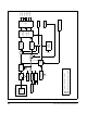

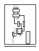
Table Of Contents
- S-3056-1 Distributed Power System SA3100 Drive Configuration and Programming Instruction Manual
- Important User Information
- Contents
- List of Figures
- List of Tables
- Chapter 1 Introduction
- Chapter 2 Configuring the UDC Module, Regulator Type, and Parameters
- 2.1 Adding a Universal Drive Controller (UDC) Module
- 2.2 Entering the Drive Parameters
- 2.3 Configuring the Vector with Constant Power Regulator
- 2.4 Configuring the Volts per Hertz (V/Hz) Regulator
- 2.5 Configuring Flex I/O
- 2.6 Generating Drive Parameter Files and Printing Drive Parameters
- Chapter 3 Configuring the UDC Module’s Registers
- 3.1 Register and Bit Reference Conventions Used in this Manual
- 3.2 Flex I/O Port Registers (Registers 0-23)
- 3.3 UDC/PMI Communication Status Registers (Registers 80-89/1080-1089)
- 3.4 Command Registers (Registers 100-199/1100-1199)
- 3.5 Feedback Registers (Registers 200-299/1200-1299)
- 3.6 Application Registers (Registers 300-599, Every Scan) (Registers 1300-1599, Every Nth Scan)
- 3.7 UDC Module Test I/O Registers (Registers 1000-1017)
- 3.8 Interrupt Status and Control Registers (Registers 2000-2047)
- Chapter 4 Application Programming for DPS Drive Control
- Chapter 5 On-Line Operation
- Appendix A SA3100 Vector Regulator Register Reference
- Appendix B SA3100 Volts / Hertz Regulator Register Reference
- Appendix C SA3100 Local Tunable Variables
- Appendix D Vector with Constant Power Regulator
- Appendix E Volts per Hertz (V/Hz) Regulator
- Appendix F Status of Data in the AutoMax Rack After a STOP_ALL Command or STOP_ALL Fault
- Appendix G Torque Overload Ratio Parameter Precautions
- Appendix H Default Carrier Frequency and Carrier Frequency Limit for Drive Horsepower Ranges
- Appendix I Vector with Constant Power Parameter Entry Example
- Index

Vector with Constant Power Regulator
D-1
APPENDIX D
Vector with Constant Power
Regulator
SA3100 drives may use either a vector regulator (constant torque or constant power)
to control current (torque) to AC motors, or a Volts per Hertz regulation algorithm (see
Appendix E). Execution of the vector algorithm is referred to as the minor loop (V/Hz
does not use a current minor loop). Power conversion (DC bus to AC variable
frequency, variable torque) is performed via pulse width modulation (PWM), which
produces a nearly sinusoidal current waveform.
A block diagram of the Vector with Constant Power control algorithm is shown on the
following page. Please refer to this figure while reading the following description.
The UDC application control task (the major loop) passes the torque reference
command in TRQ_REF% (register 102/1102) to the PMI Regulator, where a value of
+/- 4095 corresponds to the motor overload ratio amps specified for the motor in
parameter configuration. Drive A and drive B each receive their torque reference from
separate speed loops in the UDC module.
The motor currents are separated into two components, Iq and Id. The Iq component
produces the torque in the motor while the Id component is the magnetizing current
that produces the flux in the motor.
The Id component is normally calculated by the PMI processor based on the no-load
stator current configuration parameter entered by the programmer. The programmer
can select to calculate Id in the UDC task instead in order to operate the motor at
speed ratios up to 2:1 (motor speed versus base speed) or to control the flux directly.
For constant power operation at speed ratios up to 4:1, the programmer can select to
have the PMI Regulator calculate the value of Id using integrated motor voltage
feedback. The vector algorithm combines the Id and Iq components to produce a
vector that is equal to the total current required by the motor to produce the desired
torque.
The vector algorithm calculates the electrical phase position of the current reference.
This is determined from the Id and Iq reference vector, the motor speed feedback, and
the slip calculation. The outputs of the vector algorithm are three current reference
signals (Iu, Iw, Iv), one for each phase of the motor.
These current reference signals are compared with the current feedback signals,
producing error signals that feed proportional plus integral function blocks. The output
of these blocks is a voltage reference. The line-to-neutral voltage signal is further
conditioned by injecting a 3rd harmonic signal designed to increase the fundamental
voltage of the drive’s output. The conditioned voltage reference is then compared
against a triangle wave. The output of the comparator block is a PWM waveform,
which drives the power devices in the inverter bridge to pass current to the motor.