
Instruction Manual
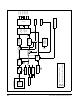

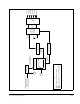
Table Of Contents
- S-3056-1 Distributed Power System SA3100 Drive Configuration and Programming Instruction Manual
- Important User Information
- Contents
- List of Figures
- List of Tables
- Chapter 1 Introduction
- Chapter 2 Configuring the UDC Module, Regulator Type, and Parameters
- 2.1 Adding a Universal Drive Controller (UDC) Module
- 2.2 Entering the Drive Parameters
- 2.3 Configuring the Vector with Constant Power Regulator
- 2.4 Configuring the Volts per Hertz (V/Hz) Regulator
- 2.5 Configuring Flex I/O
- 2.6 Generating Drive Parameter Files and Printing Drive Parameters
- Chapter 3 Configuring the UDC Module’s Registers
- 3.1 Register and Bit Reference Conventions Used in this Manual
- 3.2 Flex I/O Port Registers (Registers 0-23)
- 3.3 UDC/PMI Communication Status Registers (Registers 80-89/1080-1089)
- 3.4 Command Registers (Registers 100-199/1100-1199)
- 3.5 Feedback Registers (Registers 200-299/1200-1299)
- 3.6 Application Registers (Registers 300-599, Every Scan) (Registers 1300-1599, Every Nth Scan)
- 3.7 UDC Module Test I/O Registers (Registers 1000-1017)
- 3.8 Interrupt Status and Control Registers (Registers 2000-2047)
- Chapter 4 Application Programming for DPS Drive Control
- Chapter 5 On-Line Operation
- Appendix A SA3100 Vector Regulator Register Reference
- Appendix B SA3100 Volts / Hertz Regulator Register Reference
- Appendix C SA3100 Local Tunable Variables
- Appendix D Vector with Constant Power Regulator
- Appendix E Volts per Hertz (V/Hz) Regulator
- Appendix F Status of Data in the AutoMax Rack After a STOP_ALL Command or STOP_ALL Fault
- Appendix G Torque Overload Ratio Parameter Precautions
- Appendix H Default Carrier Frequency and Carrier Frequency Limit for Drive Horsepower Ranges
- Appendix I Vector with Constant Power Parameter Entry Example
- Index
D-2
SA3100 Drive Configuration and Programming
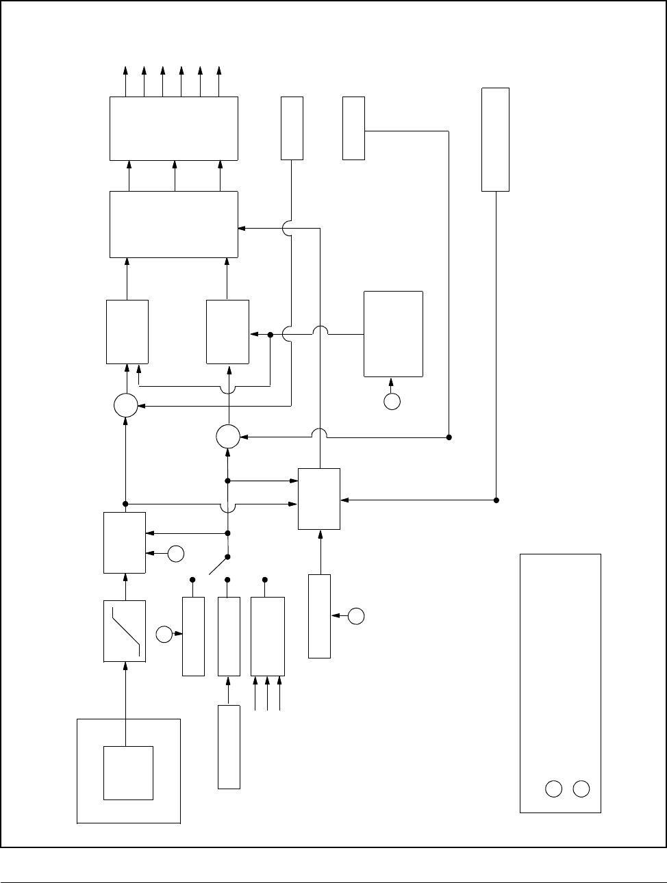
Figure D.1 – Vector with Constant Power Regulator Block Diagram
UDC MODULE
OUTER
CONTROL
LOOP(S)
TRQ_REF%
+4095
-4095
SCALING
STATOR_IZ_E1%
SLIP_ADJ_E3%
SLIP
GAIN
C
T
T
SUM
SUM
VQ_REF
Vu
Vv
Vw
P
W
M
Iu UPPER
Iv UPPER
Iw UPPER
Iu LOWER
Iv LOWER
Iw LOWER
CURRENT
REGULATION
CML_WCO%
STATOR_R_E4%
STATOR_T_E4%
T
RESOLVER POSITION
IQ_FB%
ID_FB%
+
_
+
_
VD_REF
IQ_REF
ID_REF
C
T
= TUNABLE OR AFFECTED BY TUNABLE
= DERIVED FROM CONFIGURATION PARAMETER
KEY
VECTOR
ROTATOR
CONVERSION
3-PHASE
CURRENT
REGULATION
(ANGLE OF VECTOR)
θ
FLUX REF/UDC
FLUX LOOP
STATOR_IZ%
Vu
Vv
Vw
OR
OR
&
TO