
Instruction Manual
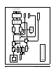
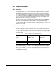

Table Of Contents
- S-3056-1 Distributed Power System SA3100 Drive Configuration and Programming Instruction Manual
- Important User Information
- Contents
- List of Figures
- List of Tables
- Chapter 1 Introduction
- Chapter 2 Configuring the UDC Module, Regulator Type, and Parameters
- 2.1 Adding a Universal Drive Controller (UDC) Module
- 2.2 Entering the Drive Parameters
- 2.3 Configuring the Vector with Constant Power Regulator
- 2.4 Configuring the Volts per Hertz (V/Hz) Regulator
- 2.5 Configuring Flex I/O
- 2.6 Generating Drive Parameter Files and Printing Drive Parameters
- Chapter 3 Configuring the UDC Module’s Registers
- 3.1 Register and Bit Reference Conventions Used in this Manual
- 3.2 Flex I/O Port Registers (Registers 0-23)
- 3.3 UDC/PMI Communication Status Registers (Registers 80-89/1080-1089)
- 3.4 Command Registers (Registers 100-199/1100-1199)
- 3.5 Feedback Registers (Registers 200-299/1200-1299)
- 3.6 Application Registers (Registers 300-599, Every Scan) (Registers 1300-1599, Every Nth Scan)
- 3.7 UDC Module Test I/O Registers (Registers 1000-1017)
- 3.8 Interrupt Status and Control Registers (Registers 2000-2047)
- Chapter 4 Application Programming for DPS Drive Control
- Chapter 5 On-Line Operation
- Appendix A SA3100 Vector Regulator Register Reference
- Appendix B SA3100 Volts / Hertz Regulator Register Reference
- Appendix C SA3100 Local Tunable Variables
- Appendix D Vector with Constant Power Regulator
- Appendix E Volts per Hertz (V/Hz) Regulator
- Appendix F Status of Data in the AutoMax Rack After a STOP_ALL Command or STOP_ALL Fault
- Appendix G Torque Overload Ratio Parameter Precautions
- Appendix H Default Carrier Frequency and Carrier Frequency Limit for Drive Horsepower Ranges
- Appendix I Vector with Constant Power Parameter Entry Example
- Index
Vector with Constant Power Regulator
D-3
D.1 Dual Wound Motor
D.1.1 Overview
The dual wound motor is a specially designed motor which has two sets of terminals
for connection to two inverters. The outputs of the inverters are connected to the
parallel windings of the motor. This type of motor enables an application engineer to
use a larger horsepower motor than the horsepower of the largest inverter. To enable
the coordination between two SA3100 inverters, both inverters must be connected to
the same UDC card (the A-channel inverter is defined as the master unit). Register
700/1700 bit 14 must be asserted in each inverter.
The drives can be commissioned in the normal fashion, however, the resulting IGN
table from the A-channel inverter will be copied to the B-channel inverter. After
commissioning, both IGN tables are identical for the two drives. The application task in
the UDC will copy registers 217 and 218 from the A-channel inverter to registers 1104
and 1107, respectively.
D.1.2 Handshake Registers
After the inverters have been initially tuned, the VOA enable bit (bit 6 of register 1100)
must be set while the inverters are running. This bit causes the B-channel inverter to
follow the A-channel inverter vector orientation. The B-channel inverter indicates that
it is successfully following the A-channel inverter by asserting the VOA_OK@ bit (bit 7
of register 1200).
The configuration data for the drives is also modified. As mentioned above, the Dual
Winding bit is set in register 700/1700. The value in register 706 is set to 15. The
value in register 1706 is set to 16. The motor nameplate horsepower and current is
divided by two and set appropriately in the configuration registers. Note horsepower is
in watts divided by 10 units.
Table D.1 – Dual Wound Motor Handshake Registers
Register Number Normal Configuration Dual Wound
217 RPM Feedback ID Reference
218 Slip Frequency Vector Orientation
1104 Auxiliary Reference Id Reference
1107 - Vector Orientation