
Instruction Manual
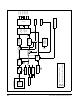

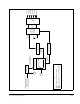
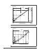
Table Of Contents
- S-3056-1 Distributed Power System SA3100 Drive Configuration and Programming Instruction Manual
- Important User Information
- Contents
- List of Figures
- List of Tables
- Chapter 1 Introduction
- Chapter 2 Configuring the UDC Module, Regulator Type, and Parameters
- 2.1 Adding a Universal Drive Controller (UDC) Module
- 2.2 Entering the Drive Parameters
- 2.3 Configuring the Vector with Constant Power Regulator
- 2.4 Configuring the Volts per Hertz (V/Hz) Regulator
- 2.5 Configuring Flex I/O
- 2.6 Generating Drive Parameter Files and Printing Drive Parameters
- Chapter 3 Configuring the UDC Module’s Registers
- 3.1 Register and Bit Reference Conventions Used in this Manual
- 3.2 Flex I/O Port Registers (Registers 0-23)
- 3.3 UDC/PMI Communication Status Registers (Registers 80-89/1080-1089)
- 3.4 Command Registers (Registers 100-199/1100-1199)
- 3.5 Feedback Registers (Registers 200-299/1200-1299)
- 3.6 Application Registers (Registers 300-599, Every Scan) (Registers 1300-1599, Every Nth Scan)
- 3.7 UDC Module Test I/O Registers (Registers 1000-1017)
- 3.8 Interrupt Status and Control Registers (Registers 2000-2047)
- Chapter 4 Application Programming for DPS Drive Control
- Chapter 5 On-Line Operation
- Appendix A SA3100 Vector Regulator Register Reference
- Appendix B SA3100 Volts / Hertz Regulator Register Reference
- Appendix C SA3100 Local Tunable Variables
- Appendix D Vector with Constant Power Regulator
- Appendix E Volts per Hertz (V/Hz) Regulator
- Appendix F Status of Data in the AutoMax Rack After a STOP_ALL Command or STOP_ALL Fault
- Appendix G Torque Overload Ratio Parameter Precautions
- Appendix H Default Carrier Frequency and Carrier Frequency Limit for Drive Horsepower Ranges
- Appendix I Vector with Constant Power Parameter Entry Example
- Index

Volts per Hertz (V/Hz) Regulator
E-1
APPENDIX E
Volts per Hertz (V/Hz)
Regulator
The SA3100 volts per hertz regulator (figure E.1) uses an application dependent V/Hz
characteristic curve to control the output voltage for a commanded frequency. The
drive’s output voltage varies with output frequency according to the V/Hz
characteristic curve, when operating in the constant torque region (V/Hz = constant).
Constant power and variable torque characteristics are supported.
The volts per hertz regulator supports a frequency range of 0 to 600 Hz. Constant
power, constant torque, and variable torque V/Hz characteristics are supported. In
the constant torque range (0 Hz to 600 Hz), a constant ratio of voltage/frequency (V/
Hz) provides, generally, a constant motor torque. Constant power may be selected
from 15 Hz to 600 Hz, enabling constant torque operation from 0 Hz to 15 Hz, and
constant power operation from 15 to 600 Hz.
The regulator provides selection of either synchronous carrier operation or fixed
carrier frequency, asynchronous carrier operation. It also provides for specification of
an adjustable frequency ramp rate to limit the rate of change in the frequency output.
The application task in the UDC controls frequency, rate of change of frequency,
minimum frequency, avoidance frequencies, and voltage boost
1
.
At low frequencies, constant torque operation cannot be maintained without an
increase in the voltage applied to the motor terminals. Voltage boost is used to modify
the linear V/Hz characteristic at low frequencies by specifying the amount of voltage
increase at a specific frequency.
To support increased breakaway torque, an offset voltage may be specified at zero
hertz. The offset voltage increases the voltage at zero frequency by the amount of the
offset voltage specified. This offset voltage function offsets the origin of the V/Hz
characteristic curve.
The open loop SA3100 V/Hz inverter may be used in closed loop configurations, such
as slip loop control by using the Frequency and Boost Voltage
1
command inputs. Slip
loop control uses rotor speed feedback to command the base operating frequency of
the V/Hz inverter. Speed error is used to control the addition, or subtraction, of a
limited frequency to the base operating frequency, as well as providing a boost
voltage to the output.
The option of current limit uses monitored phase currents to control the inverter
operating frequency as required by the application. A current IET is provided to
protect the inverter from destructive currents.
1. The term “voltage boost” refers to a change to the volts per hertz characteristic (i.e., a change on
the curve). “Boost Voltage” is an auxiliary voltage command augmenting the regulator output.