
Instruction Manual
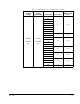
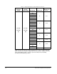
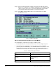
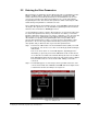
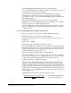
Table Of Contents
- S-3056-1 Distributed Power System SA3100 Drive Configuration and Programming Instruction Manual
- Important User Information
- Contents
- List of Figures
- List of Tables
- Chapter 1 Introduction
- Chapter 2 Configuring the UDC Module, Regulator Type, and Parameters
- 2.1 Adding a Universal Drive Controller (UDC) Module
- 2.2 Entering the Drive Parameters
- 2.3 Configuring the Vector with Constant Power Regulator
- 2.4 Configuring the Volts per Hertz (V/Hz) Regulator
- 2.5 Configuring Flex I/O
- 2.6 Generating Drive Parameter Files and Printing Drive Parameters
- Chapter 3 Configuring the UDC Module’s Registers
- 3.1 Register and Bit Reference Conventions Used in this Manual
- 3.2 Flex I/O Port Registers (Registers 0-23)
- 3.3 UDC/PMI Communication Status Registers (Registers 80-89/1080-1089)
- 3.4 Command Registers (Registers 100-199/1100-1199)
- 3.5 Feedback Registers (Registers 200-299/1200-1299)
- 3.6 Application Registers (Registers 300-599, Every Scan) (Registers 1300-1599, Every Nth Scan)
- 3.7 UDC Module Test I/O Registers (Registers 1000-1017)
- 3.8 Interrupt Status and Control Registers (Registers 2000-2047)
- Chapter 4 Application Programming for DPS Drive Control
- Chapter 5 On-Line Operation
- Appendix A SA3100 Vector Regulator Register Reference
- Appendix B SA3100 Volts / Hertz Regulator Register Reference
- Appendix C SA3100 Local Tunable Variables
- Appendix D Vector with Constant Power Regulator
- Appendix E Volts per Hertz (V/Hz) Regulator
- Appendix F Status of Data in the AutoMax Rack After a STOP_ALL Command or STOP_ALL Fault
- Appendix G Torque Overload Ratio Parameter Precautions
- Appendix H Default Carrier Frequency and Carrier Frequency Limit for Drive Horsepower Ranges
- Appendix I Vector with Constant Power Parameter Entry Example
- Index
2-2
SA3100 Drive Configuration and Programming
Step 4. Select a product type and a regulator (control) type for both drive A and
drive B. See section 2.1.1 for regulator selection rules. The remainder of this
chapter assumes that you have selected an SA3100 Drive Product with a
Vector with Constant Power Regulator or Volts/Hertz Regulator.
Step 5. Select OK to add the UDC module to the rack and return to the Rack
Configuration screen.
Rules for Configuring/Selecting Drives for the UDC Module
The following drive configuration rules apply to all DPS systems:
1. The A and B drives do not both have to be used. You can configure only one.
2. Your A/B drive type combination is restricted only if you select an SD3000
(12-Pulse) drive, an SF3000 drive, or an SA3000 Parallel Inverters drive for either
drive A or drive B. For these products, you are restricted to the drive type
combinations shown in table 2.1. All other drive type combinations are allowed.
Figure 2.1 – Adding a UDC Module
Table 2.1 – Restricted Drive Type Combinations
If you choose for Drive A . . . Then your choices for Drive B are . . .
SD3000 12-Pulse Main SD3000 12-Pulse Auxiliary
SF3000
No PMI Attached
SD3000 (6-Pulse)
SF3000
SA3000 Parallel Inverters SA3000 Parallel Inverters Auxiliary