
Instruction Manual
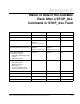


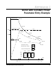
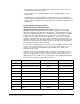
Table Of Contents
- S-3056-1 Distributed Power System SA3100 Drive Configuration and Programming Instruction Manual
- Important User Information
- Contents
- List of Figures
- List of Tables
- Chapter 1 Introduction
- Chapter 2 Configuring the UDC Module, Regulator Type, and Parameters
- 2.1 Adding a Universal Drive Controller (UDC) Module
- 2.2 Entering the Drive Parameters
- 2.3 Configuring the Vector with Constant Power Regulator
- 2.4 Configuring the Volts per Hertz (V/Hz) Regulator
- 2.5 Configuring Flex I/O
- 2.6 Generating Drive Parameter Files and Printing Drive Parameters
- Chapter 3 Configuring the UDC Module’s Registers
- 3.1 Register and Bit Reference Conventions Used in this Manual
- 3.2 Flex I/O Port Registers (Registers 0-23)
- 3.3 UDC/PMI Communication Status Registers (Registers 80-89/1080-1089)
- 3.4 Command Registers (Registers 100-199/1100-1199)
- 3.5 Feedback Registers (Registers 200-299/1200-1299)
- 3.6 Application Registers (Registers 300-599, Every Scan) (Registers 1300-1599, Every Nth Scan)
- 3.7 UDC Module Test I/O Registers (Registers 1000-1017)
- 3.8 Interrupt Status and Control Registers (Registers 2000-2047)
- Chapter 4 Application Programming for DPS Drive Control
- Chapter 5 On-Line Operation
- Appendix A SA3100 Vector Regulator Register Reference
- Appendix B SA3100 Volts / Hertz Regulator Register Reference
- Appendix C SA3100 Local Tunable Variables
- Appendix D Vector with Constant Power Regulator
- Appendix E Volts per Hertz (V/Hz) Regulator
- Appendix F Status of Data in the AutoMax Rack After a STOP_ALL Command or STOP_ALL Fault
- Appendix G Torque Overload Ratio Parameter Precautions
- Appendix H Default Carrier Frequency and Carrier Frequency Limit for Drive Horsepower Ranges
- Appendix I Vector with Constant Power Parameter Entry Example
- Index

Status of Data in the AutoMax Rack After a STOP_ALL Command or STOP_ALL Fault
F-1
APPENDIX F
Status of Data in the AutoMax
Rack After a STOP_ALL
Command or STOP_ALL Fault
AutoMax Processor UDC Module PMI Processor
LOCAL tunable variables retained retained retained
LOCAL variables retained reset to 0 N/A
COMMON memory variables non-volatile are
retained;
others are reset to 0
N/A N/A
I/O variables
(including UDC dual port memory
inputs retained and
updated;
outputs are reset to 0
inputs retained and
updated;
outputs are reset to 0
all I/O is reset to 0
Input values, including:
Feedback registers
UDC/PMI communication status
registers
UDC Error Log info
retained retained N/A
Output values, including:
Command registers
Application registers
ISCR registers
Scan-per-interrupt register
Scans-per-interrupt counter
reset to 0 reset to 0 N/A
Parameter configuration variables N/A retained N/A
UDC test switch information N/A retained N/A
D/A setup configuration N/A retained N/A
Operating system retained retained retained