
Instruction Manual
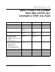

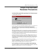

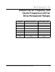

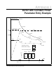
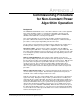
Table Of Contents
- S-3056-1 Distributed Power System SA3100 Drive Configuration and Programming Instruction Manual
- Important User Information
- Contents
- List of Figures
- List of Tables
- Chapter 1 Introduction
- Chapter 2 Configuring the UDC Module, Regulator Type, and Parameters
- 2.1 Adding a Universal Drive Controller (UDC) Module
- 2.2 Entering the Drive Parameters
- 2.3 Configuring the Vector with Constant Power Regulator
- 2.4 Configuring the Volts per Hertz (V/Hz) Regulator
- 2.5 Configuring Flex I/O
- 2.6 Generating Drive Parameter Files and Printing Drive Parameters
- Chapter 3 Configuring the UDC Module’s Registers
- 3.1 Register and Bit Reference Conventions Used in this Manual
- 3.2 Flex I/O Port Registers (Registers 0-23)
- 3.3 UDC/PMI Communication Status Registers (Registers 80-89/1080-1089)
- 3.4 Command Registers (Registers 100-199/1100-1199)
- 3.5 Feedback Registers (Registers 200-299/1200-1299)
- 3.6 Application Registers (Registers 300-599, Every Scan) (Registers 1300-1599, Every Nth Scan)
- 3.7 UDC Module Test I/O Registers (Registers 1000-1017)
- 3.8 Interrupt Status and Control Registers (Registers 2000-2047)
- Chapter 4 Application Programming for DPS Drive Control
- Chapter 5 On-Line Operation
- Appendix A SA3100 Vector Regulator Register Reference
- Appendix B SA3100 Volts / Hertz Regulator Register Reference
- Appendix C SA3100 Local Tunable Variables
- Appendix D Vector with Constant Power Regulator
- Appendix E Volts per Hertz (V/Hz) Regulator
- Appendix F Status of Data in the AutoMax Rack After a STOP_ALL Command or STOP_ALL Fault
- Appendix G Torque Overload Ratio Parameter Precautions
- Appendix H Default Carrier Frequency and Carrier Frequency Limit for Drive Horsepower Ranges
- Appendix I Vector with Constant Power Parameter Entry Example
- Index
Torque Overload Ratio Parameter Precautions
G-1
APPENDIX G
Torque Overload Ratio
Parameter Precautions
The maximum RMS current that will be generated by the Power Module based on the
entered Torque Overload Ratio must be within the limits of the selected Power Module
or a warning will be generated:
* Power Module Rated Amps for the selected Power Module.
In some cases, however, the internal limit checking rules may be too conservative and
generate a warning even when the Power Module Rated Current and Torque
Overload Ratio values are consistent. It is not unusual for an application to
momentarily exceed the continuous full load current rating of the Power Module, e.g.,
150% for one minute.
When the Power Module continuous current rating is exceeded, it is the responsibility
of the application programmer to ensure that the maximum Power Module RMS
current rating is not exceeded. The above warning provides a flag to the user to check
that the proper application programs are in place to protect the Power Module by not
exceeding the maximum Power Module ratings.
The data entered by the programmer is checked by multiplying the Motor Full Load
Current by the specified Torque Overload Ratio. If the resulting current exceeds the
current rating of the Power Module, the warning is displayed. The checking algorithm
assumes that motor current and torque are proportional, although this may not be
completely accurate.
Internal limit checking for this parameter cannot be performed more accurately
because the magnetizing component of the current (Iz) is not available until tuning is
enabled in the PMI Regulator. Tuning, in turn, cannot be performed until the
parameter object file and UDC task have been loaded to the UDC.
In order to determine if it is permissible to proceed with the application data entry
when the warning appears, a more accurate approximation of the maximum RMS
current that is required for a specific Torque Overload Ratio level may be obtained by
applying the following equation for the current vector magnitudes:
∗