
Instruction Manual


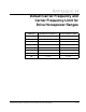

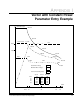
Table Of Contents
- S-3056-1 Distributed Power System SA3100 Drive Configuration and Programming Instruction Manual
- Important User Information
- Contents
- List of Figures
- List of Tables
- Chapter 1 Introduction
- Chapter 2 Configuring the UDC Module, Regulator Type, and Parameters
- 2.1 Adding a Universal Drive Controller (UDC) Module
- 2.2 Entering the Drive Parameters
- 2.3 Configuring the Vector with Constant Power Regulator
- 2.4 Configuring the Volts per Hertz (V/Hz) Regulator
- 2.5 Configuring Flex I/O
- 2.6 Generating Drive Parameter Files and Printing Drive Parameters
- Chapter 3 Configuring the UDC Module’s Registers
- 3.1 Register and Bit Reference Conventions Used in this Manual
- 3.2 Flex I/O Port Registers (Registers 0-23)
- 3.3 UDC/PMI Communication Status Registers (Registers 80-89/1080-1089)
- 3.4 Command Registers (Registers 100-199/1100-1199)
- 3.5 Feedback Registers (Registers 200-299/1200-1299)
- 3.6 Application Registers (Registers 300-599, Every Scan) (Registers 1300-1599, Every Nth Scan)
- 3.7 UDC Module Test I/O Registers (Registers 1000-1017)
- 3.8 Interrupt Status and Control Registers (Registers 2000-2047)
- Chapter 4 Application Programming for DPS Drive Control
- Chapter 5 On-Line Operation
- Appendix A SA3100 Vector Regulator Register Reference
- Appendix B SA3100 Volts / Hertz Regulator Register Reference
- Appendix C SA3100 Local Tunable Variables
- Appendix D Vector with Constant Power Regulator
- Appendix E Volts per Hertz (V/Hz) Regulator
- Appendix F Status of Data in the AutoMax Rack After a STOP_ALL Command or STOP_ALL Fault
- Appendix G Torque Overload Ratio Parameter Precautions
- Appendix H Default Carrier Frequency and Carrier Frequency Limit for Drive Horsepower Ranges
- Appendix I Vector with Constant Power Parameter Entry Example
- Index

G-2
SA3100 Drive Configuration and Programming
Maximum RMS Current = Square Root of [(%Torque_Overload_Ratio/100)
2
x
(Rated_Motor_Current
2
- Iz
2
) + Iz
2
]
Iz is the magnetizing current component of the Power Module output stored in local
tunable variable STATOR_IZ_E1%. The value for this variable can be generated by
enabling tuning in register 100/1100, bit 1. Note that you must load a complete
parameter object file and UDC task to the UDC module before you can enable tuning.
If the calculation of the Maximum RMS Current is less than or equal to the Power
Module Rated Amps at the selected carrier frequency, the programmer may continue
entering the application data.
If the calculated Maximum RMS Current exceeds the Power Module Rated Amps,
refer to the actual motor data sheets to determine the actual current required by the
motor for the required Torque Overload Ratio. If the required current exceeds the
Maximum Power Module Current Rating, a higher rated Power Module must be used.