
Instruction Manual
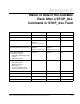

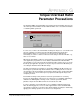

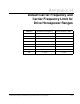

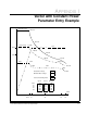
Table Of Contents
- S-3056-1 Distributed Power System SA3100 Drive Configuration and Programming Instruction Manual
- Important User Information
- Contents
- List of Figures
- List of Tables
- Chapter 1 Introduction
- Chapter 2 Configuring the UDC Module, Regulator Type, and Parameters
- 2.1 Adding a Universal Drive Controller (UDC) Module
- 2.2 Entering the Drive Parameters
- 2.3 Configuring the Vector with Constant Power Regulator
- 2.4 Configuring the Volts per Hertz (V/Hz) Regulator
- 2.5 Configuring Flex I/O
- 2.6 Generating Drive Parameter Files and Printing Drive Parameters
- Chapter 3 Configuring the UDC Module’s Registers
- 3.1 Register and Bit Reference Conventions Used in this Manual
- 3.2 Flex I/O Port Registers (Registers 0-23)
- 3.3 UDC/PMI Communication Status Registers (Registers 80-89/1080-1089)
- 3.4 Command Registers (Registers 100-199/1100-1199)
- 3.5 Feedback Registers (Registers 200-299/1200-1299)
- 3.6 Application Registers (Registers 300-599, Every Scan) (Registers 1300-1599, Every Nth Scan)
- 3.7 UDC Module Test I/O Registers (Registers 1000-1017)
- 3.8 Interrupt Status and Control Registers (Registers 2000-2047)
- Chapter 4 Application Programming for DPS Drive Control
- Chapter 5 On-Line Operation
- Appendix A SA3100 Vector Regulator Register Reference
- Appendix B SA3100 Volts / Hertz Regulator Register Reference
- Appendix C SA3100 Local Tunable Variables
- Appendix D Vector with Constant Power Regulator
- Appendix E Volts per Hertz (V/Hz) Regulator
- Appendix F Status of Data in the AutoMax Rack After a STOP_ALL Command or STOP_ALL Fault
- Appendix G Torque Overload Ratio Parameter Precautions
- Appendix H Default Carrier Frequency and Carrier Frequency Limit for Drive Horsepower Ranges
- Appendix I Vector with Constant Power Parameter Entry Example
- Index

J-2 SA3100 Drive Configuration and Programming
Note: You must observe the “Alter Speed” bit and modify the motor speed two times:
once to accelerate the motor to synchronous speed and once to cause the motor to
return to the first-point speed. Observe the “Alter Speed” bit and modify the motor
speed two times: Once to accelerate the motor to synchronous speed and once to
force the motor to return to the first-point speed. After the motor has returned to the
first point speed, observe the “tuned iz” bit (bit 10 of register 201/1201). When this bit
is asserted, the first point tuning has been accomplished. Now, the additional points
which are required by the application can be aquired in the same fashion as the
present procedure.
NOTE: While implementing the new procedure you should monitor the warning
register for bit 5 “Tune Aborted”. If this warning appears, start the commissioning
procedure over again from the first speed point.
Step by Step Commissioning Procedure
Step 1. With the drive’s motor disconnected, set bits 0 and 1 of register 101/1101.
Register 101 is for drive A and register 1101 is for drive B. Drive B can be
setup by using the register number for Drive A plus 1000.
The remaining steps use Drive A as the example.
Step 2. Command the speed loop to the appropriate speed reference.
If this is the first speed point, Do the following:
A. When the speed is reached, set bit 10 of register 101 in the UDC.
B. Monitor the “Alter Speed” status bit (bit 13 of register 201). When this bit
is set, modify the commanded speed to cause the motor to go to
synchronous speed. (Synchronous speed is equal to 120* rated
frequency/ number of motor poles eg. for a 60Hz, 4 pole motor
synchronous speed as 120*60/4 = 1800 RPM.)
C. When the motor achieves synchronous speed, the “Alter Speed” bit will
become reset, and another bit, the “Synchronous Speed Reached” (Bit 12
of register 201) becomes set.
D. Observe the “Alter Speed” status. When this bit becomes asserted, it
Commands the motor to return to the first speed point.
E. Monitor register 203. If register 203 contains a hex value of 20, reset the
warning, and try step two again.
F. If bit 10 of register 201 was set, reset bit 10 in register 101 and continue
with the next speed point as described in step 3. When all the required
speed points have been completed, go to Step 8.
Step 3. When the speed is reached, set bit 10 of register 101 in the UDC.
Step 4. Monitor register 203 and bit 10 of register 201.
Step 5. If register 203 is set to hex 20, reset bit 10 of register 101 and go to step 7.
Step 6. If bit 10 of register 201 was set, reset bit 10 in register 101 and continue with
the next speed point as described in step 3.
Step 7. If register 203 contains a hex value of 20, verify that the speed scaling of the
speed loop is correct and refer to the Notes at the end of this Appendix.
Reset the warning, continue with the next point as described in step 3.
Step 8. Reset bits 0 and 1 of register 101.
NOTE: The values saved in the IGNn! variables will be in (amps*100) units.
Note that in Dual Wound Motor Applications (Parallel Inverter Drives) you
must use the procedure described above with the following additions: