
Instruction Manual
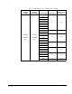
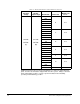
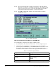
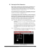
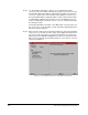
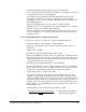
Table Of Contents
- S-3056-1 Distributed Power System SA3100 Drive Configuration and Programming Instruction Manual
- Important User Information
- Contents
- List of Figures
- List of Tables
- Chapter 1 Introduction
- Chapter 2 Configuring the UDC Module, Regulator Type, and Parameters
- 2.1 Adding a Universal Drive Controller (UDC) Module
- 2.2 Entering the Drive Parameters
- 2.3 Configuring the Vector with Constant Power Regulator
- 2.4 Configuring the Volts per Hertz (V/Hz) Regulator
- 2.5 Configuring Flex I/O
- 2.6 Generating Drive Parameter Files and Printing Drive Parameters
- Chapter 3 Configuring the UDC Module’s Registers
- 3.1 Register and Bit Reference Conventions Used in this Manual
- 3.2 Flex I/O Port Registers (Registers 0-23)
- 3.3 UDC/PMI Communication Status Registers (Registers 80-89/1080-1089)
- 3.4 Command Registers (Registers 100-199/1100-1199)
- 3.5 Feedback Registers (Registers 200-299/1200-1299)
- 3.6 Application Registers (Registers 300-599, Every Scan) (Registers 1300-1599, Every Nth Scan)
- 3.7 UDC Module Test I/O Registers (Registers 1000-1017)
- 3.8 Interrupt Status and Control Registers (Registers 2000-2047)
- Chapter 4 Application Programming for DPS Drive Control
- Chapter 5 On-Line Operation
- Appendix A SA3100 Vector Regulator Register Reference
- Appendix B SA3100 Volts / Hertz Regulator Register Reference
- Appendix C SA3100 Local Tunable Variables
- Appendix D Vector with Constant Power Regulator
- Appendix E Volts per Hertz (V/Hz) Regulator
- Appendix F Status of Data in the AutoMax Rack After a STOP_ALL Command or STOP_ALL Fault
- Appendix G Torque Overload Ratio Parameter Precautions
- Appendix H Default Carrier Frequency and Carrier Frequency Limit for Drive Horsepower Ranges
- Appendix I Vector with Constant Power Parameter Entry Example
- Index
Configuring the UDC Module, Regulator Type, and Parameters
2-3
2.2 Entering the Drive Parameters
Drive parameters are application-specific data that describe your installation’s Power
Modules, feedback devices, and motors. This information is loaded to the UDC
module, which in turn automatically downloads it to the PMI when the two are first
connected over the fiber-optic link. This information is also stored off-line with the
Programming Executive. Note that the drive parameters will be retained by the UDC
module during a Stop All fault or command to the rack.
Once a UDC module has been added to the rack, use the Zoom In command to begin
entering the drive parameters. See the AutoMax Programming Executive instruction
manual for more information on Zooming in and out.
Use the following procedure to enter the drive parameters. Section 2.3 describes how
to load the drive parameter files when you are finished. Note that if you enter drive
parameter data that is unexpected or out of range, a “warning” or “error” message will
appear on the screen. A warning message indicates that the data you have just
entered will be accepted by the Programming Executive, and you will be able to
generate drive parameter files; however, you may experience degradation of drive
performance. An error message indicates that the data you have just entered is
unacceptable, and you will not be able to generate drive parameter files.
Step 1. Zoom into the UDC module. The Power Module Interface (PMI) screen will
be displayed. You can also access this screen directly by double-clicking the
UDC module.
This screen shows either one or two PMI diagrams, depending upon the
information you previously entered. One PMI will be shown for drive A and
one for drive B, if used. Entered commands will only affect the selected drive.
Each PMI diagram will show a Flex I/O port (Port 0) and the analog or digital
Flex I/O modules that are connected to the PMI. Initially, no Flex I/O is
connected.
Step 2. The SA3100 supports one Flex I/O port, Port 0, per PMI. If Flex I/O is to be
connected to the PMI, click on Port 0. Select Add under the Configure menu
to add the Flex I/O rail to the PMI port. See figure 2.2.
Figure 2.2 – Adding Flex I/O